SOP
- 📃Enroute
- Unit General Operating Procedures
- Chapter 1 - General Operation Procedures
- Chapter 2 - South control
- Chapter 3 - North control (Tel-Aviv ACC)
- Chapter 4 - Pluto control [WIP]
- Annex A | Standard Instrument Arrivals (STARs)
- 📃Ben Gurion
- GEN | General Operating Instructions
- GEN | BGN ADC <-> BGN APC LoA
- ADC | Aerodrome Control
- APC | Approach\Departure Control
- APC | TMA Control
- APC | BGN RADAR OPERATING PROCEDURES
- APC | ANNEX
- VATIL - CVACC || LOA
- VATIL JorvACC LOA
- GEN | נהלי כלליים - General Procedures
- Berifing Area
📃Enroute
All enroute documentation for the Pluto, Tel-Aviv, and South Acc is published on this site format.
Unit General Operating Procedures
CHAPTER 1 Operating Procedures
1.1 Initial Clearance
1.1.1 Departure Clearances
All traffic from within the LLLL FIR will depart on a standard departure, either IFR, CVFR, or Military ATS, as detailed in the SOP.
Elsewhere, clearances shall be coordinated with the relevant Radar position whose departure is within their area of responsibility
1.1.2 Arrival Clearances
Aircraft inbound to airfields within the Tel-Aviv FIR should be cleared for their route/STAR by the sector that controls them before entering the TMA/CTR of their destination airport.
The responsibility for issuing said clearance varies depending on the sector being controlled, according to the table below:
| Sector | Destinations |
| Tel-Aviv ACC |
LLBG (arrival from the west) LLHA (International) |
| Pluto ACC |
LLIB LLHA (Domestic) |
| South ACC |
LLER LLBG (arrival from the south) |
1.1.2.1 Confirmation of STAR by Flight Crew
When an aircraft is transferred between Tel Aviv -> Ben Gurion, there is no need to report STAR. They are expected to continue to fly their flight-planned route.
If the previous controller has instructed the aircraft to fly a heading, the pilot will report the heading.
Where the reported STAR is correct, the controller does not need to reiterate the STAR to the pilot. Their report may be taken as confirmation that the pilot will follow the STAR, as reported.
Where the reported STAR is incorrect, the controller shall proceed as follows:
- If the routing and STAR need amending, the controller shall pass the routing and STAR instruction to the pilot in full and receive a full readback and confirmation that they can follow said route.
- If the STAR is from an outdated AIRAC cycle, the controller shall ascertain whether the pilot has the updated/correct STAR, and if yes, re-clear them on this up-to-date STAR.
If the pilot does not report the correct STAR, the controller shall pass the route to the aircraft and obtain a readback.
1.2 Use of "Expect level" Clearances
Many published STAR charts advise pilots of the levels that they should expect ATC to issue. Agreements between
Split sectors often require that certain climb/descent profiles be adhered to maintain the correct
sector coordination sequence.
- Normally, use a single transmission where the expected flight level – for
example, “ELY2431, expect 10,000 level by AMMIT, report when ready for descent”
1.3 Holding Phraseology
To reduce instances of incorrect direction holding, controllers are to use the following phraseology when
instructing aircraft to hold: “(callsign) hold at (name), (left/right) hand turns, (as published)”.
For example: “ELY40 hold at PIKOG, left-hand turns, as published”.
If there is no published hold or the direction given differs from the published hold, controllers shall also
specify the inbound course and leg time/distance.
If the pattern is used while the traffic is descending or climbing, you may add at the end of the instruction the altitude clearance, for example: “ELY2431 hold at AZERE, right-hand turns, as published, descend to FL210”.
1.4 Assumption of Electronic Aircraft Tags
The following procedures apply to all transfers of aircraft tags (Israel's internal & external).
1.4.1 Between Radar-Equipped Controllers
Controllers shall only ‘accept’ the transfer of an aircraft tag from a sending controller when the aircraft has
‘checked in’ on the receiving controller’s frequency
The transfer of an aircraft tag from a LLLL radar-equipped unit to another LLLL radar-equipped unit shall indicate
to the receiving controller that the aircraft has been identified, their Mode A code validated, and their Mode C
readout verified. However, aircraft outside of controlled airspace received from APC units should be instructed
to squawk IDENT in accordance with section 1.5.2 below.
1.4.2 Aircraft from Unstaffed Airspace
For aircraft coming from unstaffed airspace, controllers should assume the tag after sending a ‘contact me.’
request. This signals to other controllers that they are trying to contact the aircraft.
1.4.3 Departures
Controllers should not assume aircraft tags for departures until they have checked in on the frequency.
Additionally, tags of departing aircraft will not be assumed by APP controllers unless it is their responsibility to
complete identification, validation, and verification (IVV).
1.5 Surveillance Procedures
In general, the transfer of an aircraft’s tag from a LLLL radar-equipped unit to another LLLL radar-equipped unit
shall indicate to the receiving controller that the aircraft has been identified, its Mode A code validated, and
its Mode C readout verified.
1.5.1 SSR Code Allocation
Code allocation for non-local traffic is managed by the TOP-SKY Plugin. Departures joining the ATS\CVFR route
network transferred to the Area control center (ACC) from units using local SSR codes should be allocated a new general code.
For example, traffic departing Herzliya northbound with 5102 (T\A 8 SSQ).
1.5.2 Validation of SSR Mode A Codes
The display of a DUPE error (indicating a non-discrete code) on any aircraft’s tag requires the controller to
identify and validate the aircraft’s identity before issuing executive instructions, except for an initial
climb. The controller shall assign and validate a new, discrete Mode A code as soon as practicable and before transferring the aircraft to the next controller.
CHAPTER 2 Provision of Air Traffic Service
2.1 Roles and Responsibilities
▪ Provide the appropriate ATS within their stated Area of Responsibility (AoR) to ensure a safe, orderly, and expeditious
flow of air traffic.
▪ Provide Flight Information Services (FIS) where appropriate.
▪ Verify flight data, including updating and managing the flight progress strip (data block).
▪ Maintain a listening watch and conduct standard radiotelephony communication with aircraft.
▪ Provide ATS to aircraft using radar within the airspace of the relevant AoR and FIS, as
appropriate, in accordance with local procedures.
▪ Where appropriate, identify aircraft, validate, and verify SSR data on first contact or as soon as
possible thereafter.
▪ Assist aircraft in an emergency (except where the simulation of the emergency is denied in
accordance with VATSIM Code of Conduct B63).
▪ Coordinate with Military ATC as required.
▪ Individually coordinate the movement of aircraft into and out of the sector unless said aircraft are operating under the terms of a Standing Agreement.
▪ Issue releases to airfields as appropriate.
▪ Allocate or obtain levels at holding stacks.
▪ When necessary, initiate a suspension of local Standing Agreements.
▪ Issue clearances to aircraft to join, leave, or cross regulated/controlled airspace.
▪ When aircraft are accepted into the sector, ensure separation exists in accordance with this
SOP.
▪ Confirm all data transfer, revisions, and estimates have been effected as required in the local
instructions
2.2 Flight Information Services
Controllers shall provide Flight Information Service (FIS) to all known aircraft within their Area of Responsibility (AoR) in accordance with Israel AIP (PAMAT) "א-07." This service includes:
-
Weather Information: Providing information regarding known severe weather conditions.
-
Navigation Assistance: Assisting pilots who observe severe weather and request to deviate from their route. The controller shall facilitate the deviation while considering safety limitations and current air traffic.
2.3 Area Control Service
2.3.1 General Operating Requirements
-
Clearances: Any pilot operating within controlled airspace is mandatory to obtain a clearance from the appropriate ATC unit before executing any action that requires such clearance.
-
Inability to Comply: Pilots who are unable to comply with an issued clearance must immediately notify the ATC unit and request an amended clearance.
-
Flight Plans: All flights within the Tel Aviv FIR must file a flight plan and obtain an ATC clearance, maintaining continuous radio contact with the relevant unit.
-
Cruising Levels: IFR cruising levels must be maintained in accordance with the Table of Cruising Levels in AIP ENR 1.7.
2.3.2 Coordination of Special Activities and Emergency Simulations
Certain activities require specific coordination and prior approval from the ATC unit before they can be initiated:
-
Emergency Simulations: Practices of abnormal situations (e.g., forced landings, priority requests, communication failures, or loss of orientation) within a CTR or on traffic routes must be coordinated and approved as a simulation before commencement.
-
Special Flights: Formation flights, calibration flights, and photography flights require prior coordination and approval from the ATC unit.
2.4 Prioritisation of Services
-
Controllers shall prioritise the provision of services as follows:
-
Emergency Situations: Aircraft in a state of emergency or those executing an approved emergency simulation.
-
IFR Traffic: Provision of Air Traffic Control service to IFR flights operating on ATS routes.
-
CVFR/VFR Traffic: Provision of services to controlled VFR flights within their defined areas.
-
Information Services: Provision of Flight Information Services (FIS) to other participating aircraft.
-
2.4.1 Top-Down Service Provision
In the absence of local ATC, Area Controllers shall provide a top-down service at aerodromes within their AoR
where an Air Traffic Control service would normally be provided. Provision of ATS to airborne traffic should generally take priority over top-down service provision.
Where necessary, controllers may reduce the extent of the top-down service by permitting aircraft to self-manoeuvre or depart at their discretion. Aircraft should be instructed to maintain a listening watch on the frequency and must not be transferred to Unicom.
While some top-down service degradation is permitted, when the overall traffic workload (En Route and top-down) is such that safety, efficiency, or the experience of pilots is compromised, Area Controllers are to reduce
their coverage area. It is recognised that during events, reducing coverage may not be possible.
CHAPTER 3 Local Separation Standards
3.1 General
Separation shall be applied in accordance with Israel AIP Part "א" Section א, Chapter 1, Separation
Standards.

Standard vertical or horizontal separation shall be provided between:
- IFR flights and VFR flights;
- IFR flights and other IFR flights
- Special VFR flights and other Special VFR flights.
3.2 Vertical Separation
Vertical separation exists when the vertical distance between aircraft is never less than the prescribed
minimum. The vertical separation minima are:
- Between aircraft flying subsonic:
- Up to FL410 apply 1000 ft;
- b. Above FL410, apply 2000 ft.
- Where at least one of the aircraft is flying supersonic, the vertical separation required is 5000ft

3.3 Separation Based on ATS Surveillance System Information
3.3.1 Radar Separation Minima
The standard minimum horizontal radar separation to be applied across all of LLLL sectors is 5 NM, except LLBG_APP
where the use of 3 NM has been approved.
Where there is a requirement for an increase in separation or spacing between aircraft before transfer, this
shall be noted in the relevant section(s) of this document.
3.3.2 Ensuring Radar Separation
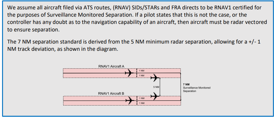
The minimum radar separation is an absolute minimum. Therefore, aircraft should not be permitted to fly on
their own navigation where the minimum separation is not ensured. As a guide, it is recommended that where
planned separation is less than 10 NM, aircraft should be on assigned headings to ensure separation. This may
be reduced to 7 NM where the use of 3 NM lateral separation has been approved.
It should be noted that due to the nature of VATSIM, headings may need to be assigned where planned
separation is greater than required, where there is the possibility of differing aircraft performance. When
operating at or close to the radar separation or surveillance monitored separation minima, controllers shall
monitor the flights for any unforeseen discrepancy.
Greater separation may be required for wake turbulence separation purposes.
The use of adequate speed control may be used in place of headings for aircraft flying in trail.
3.3.2 Surveillance Monitored Separation
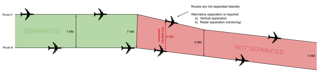
Radar monitoring of traffic on ATS routes (including SIDs, STARs, and associated holds) or FRA directs is
permitted, subject to the following conditions:
- Traffic must be established on the route centreline, or following radar vectoring / within FRA, more
than 7 NM (or 5 NM where 3 NM radar separation is approved) from the adjacent route and cleared
to a navigational fix. - Aircraft must be radar vectored if any significant route deviations are observed by the controller.
- Where turbulence or weather systems are reported, the controller must consider re-establishing
Positive radar control to counter track deviation. - Controllers should, where possible, ensure that the routes’ centrelines or the associated navigational
fix’s symbols are displayed when radar monitoring is in use.
3.3.3 Use of 3 NM Radar Separation
The use of 3NM Radar separation is approved only at LLBG_APP
3.4 Wake Turbulence Separation Requirements
Minimum of 5 NM between a HEAVY (including a SUPER) and a MEDIUM (UPPER and LOWER), SMALL
or LIGHT aircraft following or crossing behind at the same level or less than 1,000 ft below.
3.5 Minimum Separation Between Sectors
Controllers shall not route or vector unknown traffic closer than 2.5 NM from a sector boundary without prior
coordination with the adjacent sector controller.
3.6 Separation Requirements Against Holding Aircraft
A minimum of 5 NM radar separation shall be applied between holding aircraft and en-route aircraft/aircraft
approaching the holding facility. This may be reduced to 3 NM radar separation, provided that all conditions are met
relating to its use are met.
Note: Controllers should use caution when applying radar separation to aircraft approaching/passing
other holding aircraft, considering factors such as variable rates of climb/descent, hold entry patterns,
hold protected areas, and weather conditions (particularly prevailing wind).
CHAPTER 4 ALTIMETER SETTING PROCEDURES AND METEOROLOGY
4.1 Altimeter Setting Procedures
4.1.1 Transition Altitude
|
Transition Altitude |
Area |
|
18,000ft |
Above the Mediterranean Sea |
|
37,000ft |
Above Land |
CHAPTER 5 GENERAL COORDINATION REGULATION
5.1 Standing Agreements
A Standing Agreement is a procedure specifying conditions (and restrictions, as required) under which an
aircraft may enter another sector/controller’s airspace without individual coordination.
Aircraft must be individually coordinated when they cannot be transferred in accordance with a Standing
Agreement and are not deemed coordinated. Controllers may agree on temporary (amendments
to) Standing Agreements.
5.1.1 Conditions
An aircraft operating under a Standing Agreement shall be:
- cleared to, or at, an agreed level before transfer of communication; and
- on an agreed route or heading.
5.1.2 Transfer of Control and Communication
Unless specific restrictions are specified in the agreement, transfer of control of the aircraft under the terms of a
Standing Agreement is coincident with the transfer of communication.
The offering controller must ensure that any potential conflict with aircraft either in or entering their own
airspace is resolved before transfer of communication.
The receiving controller must continue the flight in the same general direction, not climb a descending aircraft
or descend a climbing aircraft, nor stop the aircraft at an intermediate level while it remains in the offering
controller’s airspace.
If traffic on a Standing Agreement will pass through an intermediate controller’s airspace without
communication (e.g., LLHA departures to the west (transfer to Tel Aviv but passing through Pluto)), transfer of control is normally effective at the receiving controller’s AoR boundary. Unless otherwise stated, any turns or climb/descent must be
coordinated with all controllers concerned.
5.1.3 Release for Climb or Descent
When transferred under a Standing Agreement, traffic is released for climb/descent (never both) to the
top/bottom of the offering controller’s airspace, unless the agreement specifies otherwise. On VATSIM, this
allows climb/descent into bandboxed sectors, but not for the traffic to enter another controller’s airspace.
Note: Traffic that has entered the receiving controller’s airspace must not then re-enter the offering
controller’s airspace during further climb or descent. This is more likely in bandboxed scenarios.
5.1.4 Release for Turn
When transferred under a Standing Agreement, traffic is released for a turn in the same general direction
against known traffic, including if transferred on a heading, and unless the agreement specifies otherwise. The
receiving controller must be informed if an aircraft is transferred on a heading against traffic, unknown to
them. Any turn must not take the aircraft into a third controller’s airspace without prior coordination.

If a release for turn is individually or electronically coordinated for an aircraft, the turn must not be greater than
than 45, unless a specific direction is agreed.
5.1.5 Level By Instructions
If no “level by” point is specified, the level must be reached prior to the aircraft entering the receiving sector.
However, the traffic does not have to be level at the time of the transfer of communication.
A climbing/descending agreement is indicated by an arrow. This means the aircraft does not need to be level
by the sector boundary and may continue to climb/descend to that level within the next sector’s airspace.
↑↓ | Indicates a climbing/descending agreement.
Where specified in an agreement, the “level by” point should be included in the descent clearance to ensure
the correct sector sequence. If the level specified cannot be achieved by the aircraft, the pilot in command
shall inform ATC immediately. ATC is responsible for further coordination with the appropriate sector(s).
Where an agreement for climbing outbounds specifies a level-by-point, controllers shall monitor the climb rate
and intervene/coordinate as required. Optionally, the “level by” point may be specified in the clearance.
5.1.6 Additional Coordination Requirements
If an aircraft that would normally be transferred to a sector on a Standing Agreement is routed to avoid that sector
entirely, controllers should notify the original sector that the traffic has been ‘skipped’.
Aircraft following a route for which an inbound Standing Agreement exists, but at a level higher than the
aircraft’s RFL must be individually coordinated.

5.2 Deemed Coordination of En-Route Traffic
Traffic that has reached the RFL indicated on the flight plan by the sector boundary is deemed to have been
coordinated and may be transferred by silent handover, provided that:
- The aircraft is at a correct level for the direction of flight;
- The RFL has not been changed within 30 NM of the AoR boundary; and
- No objection has been raised by the receiving controller.
Where the RFL is unusually low for the flight planned route, controllers should notify these flights to the next
sector individually.
Transfer of Control is at the receiving sector boundary, unless otherwise stated in this document.
5.3 Individual Coordination
Flights not deemed coordinated or subject to a Standing Agreement must be individually coordinated between sector controllers. An exit flight level should be offered, and other conditions may optionally be applied.
Departures from aerodromes not covered by Standing Agreements must also be allocated a level for
acceptance from the aerodrome/approach controller by the receiving sector.
Allow the receiving sector to identify the traffic before presenting the coordination request.
5.4 Transfer of Control and Communication
Unless otherwise stated in this document:
- transfer of control is effective at the common AoR boundary between the offering and receiving controllers
- transfer of communication shall take place no later than the sector boundary.
Aircraft must not enter a third controller’s airspace without coordination. This applies to all climb/descent and turn procedures detailed below and in sector instructions.
5.4.1 Release for Climb or Descent
Aircraft that are climbing/descending are released for climb/descent to the top/bottom of the transferring controller’s airspace.
5.4.2 Release for Turn
Traffic transferred on its own navigation is released for turn in the same general direction.
If an aircraft not operating under the terms of a Standing Agreement is transferred on a heading, any change
of heading, before entering the receiving controller’s airspace, must be coordinated unless otherwise
specified in sector procedures.
It is the responsibility of the receiving controller to ascertain if an aircraft is on a heading, and it should be
noted that aircraft may be transferred on a heading against traffic, unknown to the receiving sector
If a release for turn is individually or electronically coordinated for an aircraft, the turn must not be greater
than 45, unless a specific direct is agreed.
5.4.3 Full Release
A full release is an authorisation for the accepting unit to climb, descend and/or turn a specific aircraft according to the instructions above.
5.4.4 Conditions of Transfer
Aircraft transferred on a heading or with a speed restriction should have this recorded in the tag, with the pilot instructed to report their assigned heading and/or speed upon transfer of communication.
5.5 Handover
5.5.1 Silent Handover
Unless otherwise stated in this document, transfer of control between a enroute controller and an external
ACC may take place by means of a Silent Handover (that is, without prior coordination) provided that:
5.5.2 Radar Handover
Where the conditions for Silent Handover are not met, transfer of control by radar handover, the transferring controller will transfer the TAG of Said traffic and wait for acceptance; only then may the transferring controller transfer the control of the traffic.
- If the aircraft concerned are following the same route, they are spaced by a minimum of 10 NM,
constant or increasing. (See Note). - If the aircraft concerned are on crossing tracks, the conditions detailed under (Reduced) Longitudinal
Separation for the relevant ACC is met. - The transferring controller places any speed control or vectoring instructions (within the terms of the
agreement) in the tag and instructs the aircraft to report these on first contact with the receiving
controller. - The receiving controller is informed, by means of XFL electronic coordination or otherwise, of any
level restriction other than an aircraft’s requested flight level or those covered by Standing
Agreement prior to transfer of communications.
Note: The 10 NM here is not a separation standard. It is the minimum spacing required for a silent transfer of control.
5.6 Coordination of Direct Routings
There is no requirement to coordinate a direct routing for an aircraft, provided that the direct issued:
- Is entered in the data block label and/or EuroScope sector list;
- Ensures the aircraft will enter the receiving sector at the boundary with the offering sector, not
through an intermediate sector; and - Will not take the aircraft off route by more than 5 NM in the next or any subsequent sectors, or
contravene any positioning requirements specified in a Standing Agreement.
If any of the above conditions cannot be met, coordination shall be effected by the offering sector with the
receiving sector, the original receiving sector if that has changed, and any intermediate sectors through which
The aircraft will transit.
5.7 Electronic Coordination
Electronic coordination requires less time to perform (usually a few seconds) and generally lower controller
workload.
Releases between controllers may be specified via the TOPSKY Plugin Enroute Release tag item.
Additionally, some neighbouring ACCs use TopSky, which has release functionality.
The main limitation of EuroScope electronic coordination is that they are only applicable to pre-defined
scenarios and can only be initiated by one adjacent controller. Also, it is not suitable for time-critical situations
where a timely response is essential

Where electronic coordination is used to agree a transfer level, this level is always assumed to be the level by the
coordination point (or sector boundary if no defined point).
5.8 Handing Over/Taking Over an Operational Position
A Controller taking over a position must be fully aware of all relevant information before they
accept responsibility for the operational position.
Controllers are recommended to use one of the following checklists as an aid when handing over and
taking over sectors.
5.8.1 WEST
|
W |
Weather |
Turbulence |
|
CB Activity |
||
|
SIGMETs |
||
|
Winds |
||
|
Pressure Settings |
||
|
Runway(s) in Use |
||
|
E |
Equipment |
RT/Intercom systems |
|
ATIS |
||
|
S |
Situation |
Military Activity |
|
Holding |
||
|
Flow restrictions (e.g., MDI) |
||
|
Staffing/Adjacent ATC |
||
|
T |
Traffic |
Traffic on frequency |
|
Pending Traffic |
||
|
Potential Traffic Conflicts |
5.8.1 PRAWNS
|
P |
Pressure |
Pressure Settings |
|
R |
Roles |
Area Sectors – bandboxed? Splits? Frequencies? |
|
Top-down responsibilities |
||
|
A |
Airports |
Runways |
|
W |
Weather |
Turbulence, CB Activity, SIGMETs |
|
Avoidance |
||
|
Winds |
||
|
N |
Non-Standard Info |
Holding |
|
Flow restrictions (e.g., MDI) |
||
|
Amended or cancelled standing coordination |
||
|
Military Activity |
||
|
S |
Situation |
Transfer of TAGs |
|
Coordinated traffic |
CHAPTER 6 TOP-DOWN COVERAGE
In the absence of the local ATC, the responsibility for top-down control is determined as follows:
|
ID |
Sector/Position |
|
TLV |
Tel-Aviv Bandbox |
|
TLV_D |
Tel-Aviv Departures |
|
TLV_A |
Tel-Aviv Arrivals |
|
BGN_A |
Ben Gurion Arrivals |
|
BGN_D |
Ben Gurion Departures |
|
BGN_T |
Ben Gurion TMA |
|
PLT |
Pluto |
|
PLT_W |
Pluto West |
|
PLT_E |
Pluto East |
|
STC |
South |
|
Aerodromes |
Top-Down Priority (Left to Right, High to low) |
|
Ben Gurion (LLBG) |
BGN_D –BGN_T - TLV_D – TLV |
|
Eilat (LLER) |
STC – TLV |
|
Rosh Pina (LLIB) |
PLT_E - PLT – TLV_A - TLV |
|
Haifa (LLHA) |
PLT_W – PLT – TLV_A – TLV |
|
Herzelia (LLHZ) |
BGN_A – BGN_A – PLT_W – PLT – TLV_A - TLV |
CHAPTER 7 CIVIL/MILITARY PROCEDURES
Procedures relevant to multiple sectors are contained in this Chapter.
7.1 Apolo military control
To give a response to the following increase in mil TFC in the LLLL FIR, and to support the vIAF VSOA VATIL started applying LLMA c/s "APPOLO" and their splits "LIBA" for the north control and "SHANON" for the south control, as shown in the picture
Apolo control - Bandboxing/Splitting Procedures
|
LLMA_CTR "Apolo" 122.900 Mhz |
LLMA_N_CTR "Liba" 132.850 Mhz |
| Bandbox |
LLMA_S_CTR "Shanon" 122.900 Mhz |
7.2 Military Route Corridors
7.2.1 General Procedures
Military corridors are established to enable the transit of the ATS route structure by Military traffic
7.2.1.1 Apolo control online
When Apolo control is online, they will coordinate with the relevant ACC controller to update on transit in the corridor or closure of civil airspace (as explained in each ACC).
It is both Apolo control and the relevant ACC requirement to maintain separation from the corridor or the T\A; the priority is for military or "National Mission."
7.2.1.2 Apolo control offline
When Apolo control is offline, aircraft/formations wishing to transit a corridor will call the local ACC (Pluto\South\Tel-Aviv) at least 5 minutes prior to transit, while setting the V-LARA application as required. Traffic should be identified, and Mode C verified, and may be offered a service outside of the corridor or Training Area, depending on workload or knowledge.
Clerance should be in the following format:
"C/S Follow the Corridor at an altitude of XXXft report entering the area."
7.2.2 Sea corridor "Derech Ha-YAM" (דרך הים)
highlighted in red
Apolo control Sector: Liba
Civil Sector: Pluto\Tel-Aviv\BGN TMA\South
Transit Altitude: 12000ft - FL500 (With exception to BGN TMA, which is split as per the following photo), for transit in lower altitude, Apolo will request deligation from Tel-Aviv ACC

7.2.3 Netofa corridor "Derech Netofa" (דרך נטופה)
highlighted in blue
Apolo control Sector: Liba
Civil Sector: Pluto
Transit Altitude: 12000ft - 30000ft
7.2.4 Galil corridor
highlighted in purple
Apolo control Sector: Liba
Civil Sector: Pluto
Transit Altitude: 12000ft - FL500
7.2.5 Bikaa corridor "Derech Bikaa" (דרך הבקעה)
highlighted in steel blue
Apolo control Sector: Liba
Civil Sector: Pluto
Transit Altitude: 12000ft - FL500


7.2.6 Hahhar corridor "Derech Hahhar" (דרך ההר)
highlighted in brown
Apolo control Sector: Liba\Shanon
Civil Sector: Pluto\South\Tel-Aviv
Transit Altitude: 12000ft - FL500 (south of BGN-TMA), 18000ft - 26000ft (Above BGN-TMA)
7.2.7 Hahhar Hanistar corridor "Derech Hahhar Hanistar" (דרך ההר הנסתר)
highlighted in yellow
Apolo control Sector: Shanon
Civil Sector: South
Transit Altitude: 8000ft - 11000ft
7.2.8 Plugot corridor "Derech Plugot" (דרך פלוגות)
highlighted in desert yellow
Apolo control Sector: Shanon
Civil Sector: South
Transit Altitude: 12000ft - FL500
7.2.9 Hanegev corridor "Derech Hanegev" (דרך הנגב)
highlighted in pink
Apolo control Sector: Shanon
Civil Sector: South
Transit Altitude: 12000ft - FL500
7.2.10 Hanegev Hamurhevet corridor "Derech Hanegev Hamurhevet" (דרך הנגב המורחבת)
highlighted in Olive
Apolo control Sector: Shanon
Civil Sector: South
Transit Altitude: 12000ft - FL500
Chapter 1 - General Operation Procedures
1.1 Sectors and Sector Groups
Tel Aviv control manages en route traffic in the Tel Aviv (LLLL) FIR.
Israeli airspace is divided into three main sector groups based on their geographical position.
- South control: Southbound of LLBG TMA
- Tel Aviv control: Over the sea for International flights
- Pluto control: over land north of the LLBG TMA
| VATSIM Callsign | Radio C/S | Group | Frequency |
| LLLL_CTR | Tel Aviv Control | Tel Aviv | 121.400 |
| LLLL_D_CTR | Tel Aviv Control | Tel Aviv | 122.950 |
| LLLL_A_CTR | Tel Aviv Control | Tel Aviv | 121.400 |
| LLLL_E_CTR | Tel Aviv Control | Tel Aviv | 132.025 |
| LLSC_CTR | South Control | South | 120.900 |
| LLGV_CTR | Hagav | South | 128.350 |
| LLGV_N_CTR | Hagav North | South | 128.350 |
| LLGV_S_CTR | Hagav South | South | 121.150 |
| LLPT_CTR | Pluto | Pluto | 119.150 |
| LLPT_W_CTR | Pluto West | Pluto | 119.150 |
| LLPT_E_CTR | Pluto East | Pluto | 134.650 |
1.2 LLLL Bandboxing/Splitting
The table below shows the three main groups spliiting proceduresa, including ownership of sectors.
|
LLLL_D_CTR (122.950) |
LLLL_D_CTR (122.950) |
LLLL_CTR (121.400) |
LLLL_CTR (121.400) |
|
LLLL_A_CTR (121.400) |
|||
|
LLLL_E_CTR (132.025) |
|||
|
LLPT_W_CTR (119.150) |
LLPT_CTR (119.150) |
||
|
LLPT_E_CTR (134.650) |
|||
|
LLGV_N_CTR (128.350) |
LLGV_CTR (128.350) |
LLSC_CTR (120.900) |
|
|
LLGV_S_CTR (121.150) |
|||
|
LLSC_CTR (120.900) |
|||
Chapter 2 - South control
2.1 Area of Responsibility
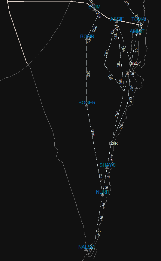
South control (LLSC_CTR) is the south sector of LLLL FIR, covering from the south line of TMA LLBG down to Eilat city.
Also in this sector are seven AF bases and a few uncontrolled airstrips. The sector is going from ground level to unlimited (if mil-certified, if not until FL370).
The sector splits mainly into Flights over the ATS route (mainly at the J10 airway, etc.) The parent unit, as shown above, is LLSC_CTR.
2.1.1 Sector Frequency
South control is operating on 120.900
2.2 General Operating Procedures
2.2.1 Common ATS traffic routing
The main traffic is either northbound or southbound, with little to no east-westbound. The traffic normally passes through the J10 airway. In the sector are some shortcuts which may be approved under the following conditions
|
Range |
Condition for approval |
Pre-Approval condition |
Identification |
|
ZFR-MZD |
none, approved and plannable |
Filed in FPL |
T94 |
|
BIRIM - NURIT |
1. Friday/Saturday 2. No military traffic active within the Q30 range
Or 1. Approval from "Apollo"\"Shanon" MIL-ACC
|
vIAF flight (VSOA remark) |
Q30 |
|
ASSIF-OBAKO |
1. Clear the area within the shortcut airway with no military traffic active (TSA Area 8)
Or
1. Approval from "applo"\"Shanon" if connected
|
CDR 2 – ONLY BY ATC |
T85 |
|
ASSIF-OBAKO |
T80 |
||
|
ASSIF-MZD |
T84 |
Remark: The bold identification may indicate the most preferred shortcuts for traffic management
2.2.2 Route restrictions
Due to a high amount of traffic in the vicinity of the south sector, most of the airways are limited to the upper limit of FL370 and the lower limit of 5000 to 6000ft.
2.2.2 ATS controlling restrictions
Due to a small maneuver area within the J10 corridor, the controller may not vector any traffic; instead, the controller MAY give direct instructions to any FIX over the route/sector.
Vectors shall be the last resort in any situation for IFR traffic
2.2.2 Initial Route Clearance and transfer of control (IFR)
South control shall issue route clearance (including STARs) in accordance with GEN 1.1. See Annex A for a list of
STARs, and as required in Chapter 2.3
2.3 Standing Agreements
2.3.1 Tel-Aviv (LLLL)
Separation: Each transfer of control will be with at least 10NM of separation between two planes with the same performance. If the lateral separation cannot be accomplished, a vertical separation of 1000ft (and steady) is required.
Altitude hold: When control is transferred to Tel Aviv while the traffic is on J10 airway, Tel-Aviv will transfer the traffic when holding coordinated altitude until leaving the said airway.
2.3.1.1 From Tel Aviv to South control
Altitude agreement
|
To |
Agreement |
Conditions |
|
LLER\LLOV |
29,000 ft at SIVAK |
20NM lateral separation (RWY19) 30NM lateral separation (RWY01) |
|
LLNV |
19,000 ft at SIVAK |
|
Transfer of control
|
Position |
Conditions |
|
DONAG |
|
|
SIVAK |
|
|
ASSIF |
If "ASSIF Shortcut" is active |
2.3.1.2 From South to Tel Aviv control
Altitude agreement
|
From |
Agreement |
Conditions |
|
LLER\LLOV |
28,000 ft at TOMAL |
Reporting 10 minutes in advance of transfer |
|
LLNV |
12,000 ft at TOMAL |
|
Transfer of control
|
Position |
Conditions |
|
YOLCO |
|
|
SIVAK |
|
2.3.2 Ben Gurion (LLBG)
Minimal Segregation zone: Both South control and Ben-Gurion will maintain a segregation zone of 2.5NM of the south border of Ben Gurion TMA (except for J10 airway or transfer of control)
WT separation from the segregation zone: When traffic that requires WT radar separation, each station will maintain half the required separation from the South border of Ben Gurion TMA
ASSIF&J10 routing: When the ASSIF shortcut is active, the J10 airway north of the join position of the shortcut will be assumed as a Northbound airway, while the approved shortcut will be assumed as a southbound airway
2.3.2.1 South to Ben Gurion
Altitude agreement
|
From |
Agreement |
Conditions |
|
ASSIF |
10,000/8,000 at ASSIF |
|
|
AMMIT |
10,000/8,000 at SIVAK |
|
Transfer of control:
|
Position |
Conditions |
|
5NM Before AMMIT |
Clear of conflict |
|
10NM Before ASSIF |
If "ASSIF Shortcut" is active and there is an entry from ASSIF |
STAR allocation: South control will allocate STAR to Ben Gurion, as explained in ANNEX A.
When no STAR is available, the south control may route the traffic with one of the following options:
1. TOMAL - ADLOD
2. ASSIF - ADLOD (If requested by Pilot or from Ben Gurion UNIT) and with the following conditions:
a. The route to ASSIF is Clear down to 8000ft
b. The traffic will be transferred as soon as possible
2.3.2.2 Ben Gurion to South
Altitude agreement
|
From |
Agreement |
Conditions |
|
LLBG\LLHZ |
9,000 ft at TOMAL/ASSIF 8000 ft at BIRIM |
*IAS of 250kts |
Required Separation:
Two international flights: When two planes are flying southbound for an international flight, they may be transferred with 10 minutes of separation.
Two LLER inbound flights: The two airplanes shall be separated by at least 5 minutes when in the same performance group.
Any other flights:
|
General |
Lateral |
Vertical |
Other instructions |
|
Following with same or reduced speed from precciding |
5NM |
No requirement |
No need |
|
Following with faster speed from precciding |
15NM or greater |
No requirement |
No need |
|
Less than 15NM |
1000ft or greater |
No need |
|
|
none |
Coordination is required |
Transfer of control:
|
Position |
Conditions |
|
TOMAL |
Clear of conflict |
|
ASSIF |
If "ASSIF Shortcut" is active and Holding Altitude as instructed |
|
BIRIM |
If "Q30 Shortcut" is active and Holding Altitude as instructed |
2.3.3 Nevatim (LLNV)
2.3.3.1 Nevatim to South
Altitude agreement
|
From |
Agreement |
Conditions |
|
MZD (Northbound) |
↑6000 at MZD |
|
|
KINAR (Southbound) |
↑7000 at KINAR |
|
Transfer of control
|
Position |
Conditions |
|
10NM Before ENOKO |
Clear of conflict |
2.3.3.2 South to Nevatim
Altitude agreement
|
From |
Agreement |
Transfer |
|
South of KINAR |
6,000 ft at MALUQ |
|
|
North of MZD |
6000 ft at MZD |
|
Transfer of control
|
Position |
Conditions |
|
2NM south of SUKOT |
From the south |
|
MZD |
From the north |
STAR allocation: South control may not allocate any STAR to Nevatim
2.3.3 Eilat (LLER)
STAR allocation: South control will allocate STAR to Eilat, as explained in ANNEX A.
2.3.3.1 From Eilat to South
Altitude agreement:
|
From |
Agreement |
Conditions |
|
LLER SID |
↑5000ft |
RWY01 |
|
|
↑8000ft |
RWY19 |
Transfer of control:
|
Position |
Conditions |
|
Airborne passing 3500ft |
RWY 01 in use |
|
Facing North |
RWY19 in use |
2.3.3.2 From South to Eilat
Altitude agreement:
|
From |
Agreement |
Conditions |
|
SHANI |
6000ft at NURIT |
RWY01 |
|
|
6000ft at ESHEL |
ADIVI-APP RWY01 |
|
|
5000ft at NURIT |
RWY19 |
Transfer of control:
|
Position |
Conditions |
|
SHANI |
|
Approval of RNP-VIS (ADIVI\NURIT): May be approved for Israeli airline only with the request of the flight crew ONLY
2.4 Coordination and Procedures with Adjacent Units, Sectors, and Airfields
2.4.1 Tel Aviv
- Inbound traffic to Nevatim: Should be coordinated to be transferred TOMAL at a steady altitude of 17,000ft
- Inbound Traffic to SIVAK: Tel Aviv may be reported in advance of 10 minutes before crossing SIVAK
- Outbound Traffic From Nevatim: South may coordinate climbing to 14,000ft
2.4.2 Ben Gurion
- Crossing SIVAK at 6000ft may be coordinated (For traffic entering LLBG_TMA)
- Entry to South from BIRIM may be coordinated and will be approved at an altitude of 8,000ft only
2.4.3 Nevatim
- Release of departing traffic: Nevatim is required to request release from South control twice for each traffic, once 5 minutes before departure and once 1 minute before departure
2.4.4 Shanon\Hagav\Appolo
When active, the following coordination is required
- Each holding pattern on J10 airway will need to be approved via MIL-control
- Each climb before entering J10 airway will need to be approved via MIL-control
- Each departure from LLRM will be coordinated with South control
The best practice is to approve ZFR\KINAR (due to active airways)
2.5 En-route Holding Procedures
MZD Hold
When a high amount of traffic is inbound to LLBG\OJAI, and the LLBG_APP is not yet able to receive it South control may use this hold to regulate the traffic and give better separation
|
VOR hold, 1.5- minute legs |
MZD |
|
001° |
Axis |
|
Left hand |
Direction |
|
10,000-37,000 |
Holding Altitude |
|
Maximum 240 kts IAS |
Speed |
ZFR Hold
When the time separation to LLER is too tight, this pattern and the next one may be used for sequencing
|
VOR hold, 1.5- minute legs |
ZFR |
|
199° |
Axis |
|
Right hand |
Direction |
|
6,000-34,000 |
Holding Altitude |
|
Maximum 265 kts IAS |
Speed |
Shayo Hold
The second holding is used to moderate LLER traffic, lower in priority due to RNAV requirement and a higher lower limit that will require a steep descent.
Chapter 3 - North control (Tel-Aviv ACC)
3.1 Area of Responsibility
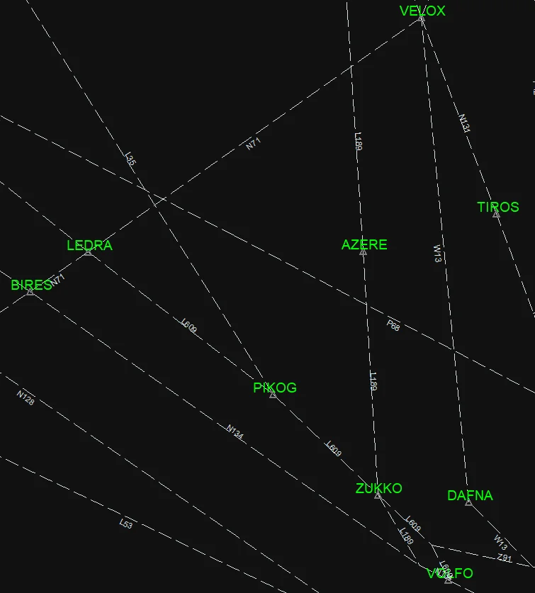
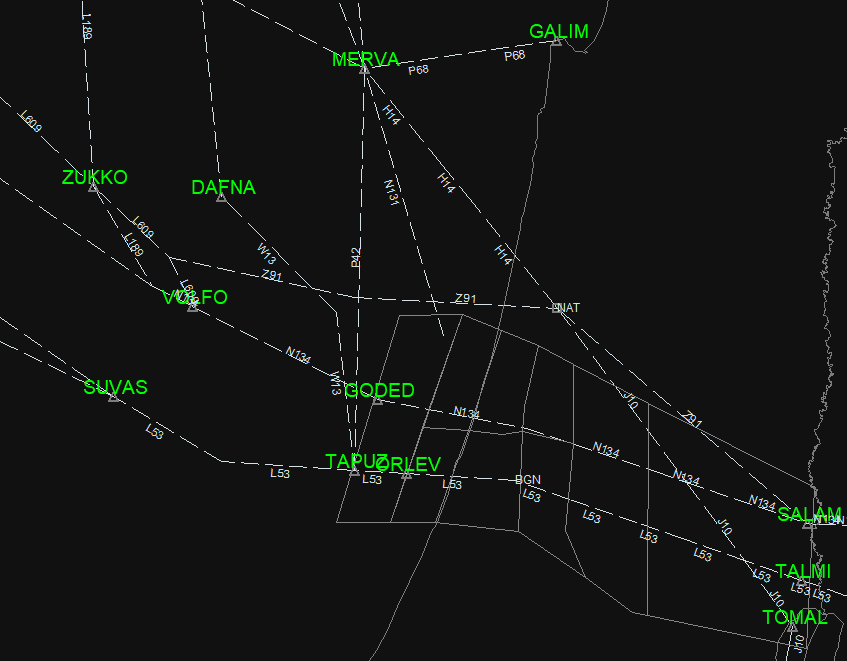
North control (LLLL_CTR) is the North sector of LLLL FIR, covering from the south line of TMA LLBG up to the northern border of the FIR above the coast and above the TMA.
The sector is splitting into 3 main sectors: Inbound to LLBG\LLHA\OJAI (LLLL_A_CTR); outbound of LLBG\LLHA\OJAI (LLLL_D_CTR); Crossing traffic at the sector (LLLL_E_CTR).
Also, there is an area between N71 airway and zukko, "The triangle which is in deligation."
3.2 General Operating Procedures
3.2.1 Route Restrictions
|
General |
Pre-Approval condition |
Explanation |
Range |
|
OVR 28-29 |
Approval (If connected) From MIL-Control |
Clear of conflict |
TALMI L53 SUVAS |
|
OVR 35 -UNL |
Approval (If connected) From MIL-Control |
Clear of conflict |
TALMI L53 SUVAS |
|
SID PATZAEL |
Coordination from MIL-CONTROL |
When activated from MIL-Control 14000ft-16000ft |
Maintain 12,000ft for inbound from AMMAN to LLLL |
|
NAT SHORCUP |
none |
Approval per traffic from MIL-control |
Lateral crossing MERVA H14 NAT Z91 SALAM |
|
9K-13K |
none |
Request for closure from military control |
Coastline -> TAPUZ |
|
YAM |
V-LARA without requests |
Area is clear |
MERVA |
|
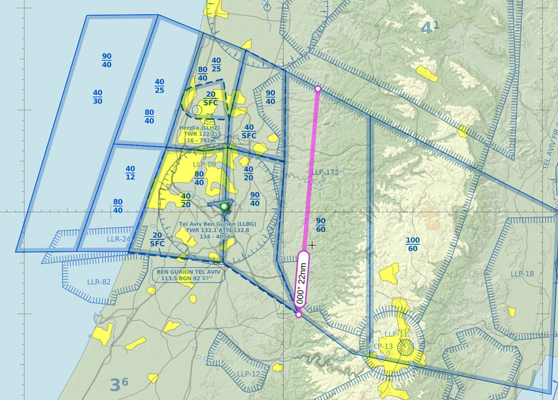
Jordanian East |
Coordination from MIL-CONTROL |
Request for closure from military control |
11000ft-15,000ft |
|
Jordanian West |
Coordination from MIL-CONTROL |
|
14,000ft-16,000ft |
Figure 1: East-West Jordanian closure
3.3 Standing Agreements
3.3.1 Haifa (LLHA)
3.3.1.1 from Haifa to Tel-Aviv
Altitude agreement:
|
From |
Agreement |
Conditions |
|
GALIM |
↑3000ft at GALIM to 5000ft |
Clear of conflict |
|
|
5000ft at GALIM |
Clear of conflict |
Transfer of control:
|
Position |
Conditions |
|
GALIM |
Steady and clear of conflict |
3.3.1.2 from Tel-Aviv to Haifa
Altitude agreement:
|
From |
Agreement |
Conditions |
|
GALIM |
5000ft at GALIM |
Clear of conflict |
Transfer of control:
|
Position |
Conditions |
|
10NM Before GALIM |
↓ 5000ft |
3.3.2 Ben Gurion (LLBG)
3.3.2.1 From Ben Gurion to Tel-Aviv
STAR allocation: Tel Aviv control will allocate STAR to Ben Gurion, as explained in ANNEX A.
Altitude agreement:
|
From |
Agreement |
Conditions |
|
LLBG SID |
↑8000ft |
Clear of conflict |
Transfer of control:
|
Position |
Conditions |
|
Airborne passing 3500ft |
VIA SID |
3.3.2.2 From Tel-Aviv to Ben Gurion
Altitude agreement:
|
TO |
Agreement |
Conditions |
|
LLBG |
↓5000ft |
RWY26/21/12/08 |
|
|
↓6000ft |
RWY30 |
Transfer of control:
|
Position |
Conditions |
|
2NM before AMMOS |
RWY26/30/21 |
|
2NM before PURLA |
RWY08 |
|
2NM before NINET |
RWY12 |
3.3.3 South Control
Separation: Each transfer of control will be with at least 10NM of separation between two planes with the same performance. If the lateral separation cannot be accomplished, a vertical separation of 1000ft (and steady) is required.
Altitude hold: When control is transferred to Tel Aviv while the traffic is on J10 airway, Tel-Aviv will transfer the traffic when holding coordinated altitude until leaving the said airway.
3.3.3.1 From Tel Aviv to South control
Altitude agreement
|
To |
Agreement |
Conditions |
|
LLER\LLOV |
29,000 ft at SIVAK |
20NM lateral separation (RWY19) 30NM lateral separation (RWY01) |
|
LLNV |
19,000 ft at SIVAK |
|
Transfer of control
|
Position |
Conditions |
|
DONAG |
|
|
SIVAK |
|
|
ASSIF |
If "ASSIF Shortcut" is active |
3.3.3.2 From South to Tel Aviv control
Altitude agreement
|
From |
Agreement |
Conditions |
|
LLER\LLOV |
28,000 ft at TOMAL |
Reporting 10 minutes in advance of transfer |
|
LLNV |
12,000 ft at TOMAL |
|
Transfer of control
|
Position |
Conditions |
|
YOLCO |
|
|
SIVAK |
|
3.3.4 Pluto
Inbound to LLHA: There are 4 main ways to enter Haifa, as will be coordinated with PLUTO
Pluto shall perform tactical clerances to avoid conflict.
- Option A: YAM is open, and the Sea military corridor is open: Entry via GALIM 3000ft
- Option B: YAM is open, and the Sea military corridor is active: Entry via GALIM 5000ft
- Option c: YAM is active, and the Sea military corridor is closed: Entry via GALIM 3000ft and MERVA 5000ft
- Option c: YAM is active, and the Sea military corridor is active: Entry via GALIM 5000ft and MERVA 5000ft
3.3.4 Nicosia
3.3.4.1 From Tel Aviv to Nicosia
Altitude agreement
|
Conditions |
Agreement |
From |
|
|
Clearance limit FL260 or below |
LLBG / LLHA |
|
|
Clearance limit FL320 |
OJAI / OJAM / LLER / LLNV |
|
|
Clearance limit is RFL |
Any other outbound |
Transfer of control
|
Conditions |
Position |
|
Westbound traffic release |
SUVAS |
|
Northbound traffic release |
FIR Boundaries |
3.3.4.2 From Nicosia to Tel Aviv
Altitude agreement
|
Conditions |
Agreement |
From |
|
(LLBG\LLER) |
↓ FL210 (No lower than FL210) |
Eastbound |
|
(LLBG\LLER) |
↓ FL270 (No lower than FL270) |
Southbound |
|
|
↓ 8000ft (No lower than 8000ft) |
LLHA Inbound |
|
|
RFL (FL330 or above) |
Overflight |
Transfer of control
|
Conditions |
Position |
|
Traffic is released to Tel-Aviv ACC as soon as crossing |
Crossing N71 Airway |
Note: All traffic from Nicosia FIR to LLLL FIR should be transferred to LLLL_CTR (or LLLL_E_CTR for overflights if LLLL_CTR is offline. If both offline, LLBG_APP for arrivals. If all offline, Unicom).
Spacing & Overflow Agreements:
-
Separation: Two or more aircraft with less than 15NM separation at the same direction will be separated by vertical separation of 2,000 ft.
-
Overflow: If Tel-Aviv ACC declares overflow, Nicosia will hold traffic between FL210 to FL340 at AZERE (Right, Inbd 172, 1.5 min, max IAS 300kts) or PIKOG (Left, Inbd 123, 1.5 min, max IAS 300kts). Transfer of control occurs only after leaving the hold.
3.3.5 Amaan
- All traffic shall hold cleared altitude 5NM Prior to transfer [unless said otherwise]
- All traffic shall be separated with lateral separation of 10NM at least unless maintaining vertical separation.
- When transfer of control is performed the traffic shall be with 45 deg of clear area until entering the receiving units' airspace
- Transfer of control will be 5NM before SALAM while holding cleared altitude
3.3.5.1 From Tel Aviv to Amman
|
Inbound |
Altitude |
Condition |
|
SALAM (enroute) |
FL360 or above |
|
|
28,000ft ALT holding |
|
|
|
OJAI |
15,000-11,000 |
· Depends on traffic at LLLL airspace · Until SALAM the traffic shall maintain LLBG-QNH |
3.3.5.2 From Amman to Tel Aviv
|
Inbound |
Altitude |
Condition |
|
MOUAB |
FL350 or above |
|
|
Departing TRFC |
12,000ft at MOUAB Cleared ↑ 14,000 Higher levels maybe coordinated especially when 08’s OJAI ops or 06 OJAM ops in use. Maximum allowable is per ATC (usually FL280) |
|
3.4 Coordination and Procedures with Adjacent Units, Sectors, and Airfields
3.4.1 Haifa (LLHA)
Departing from LLHA:
- Before start-up clearance, LLHA will request SSQ code for the departing traffic
- Haifa will request RELEASE (10 min) from Tel-Aviv
Inbound to LLHA:
- Tel-Aviv will update Haifa more than 4 min prior to arrival about the ETA to position GALIM
- Tel-Aviv will update Haifa If the inbound traffic is unable to cancel IFR.
3.4.2 Ben Gurion (LLBG)
3.4.3 South (LLSC)
- Inbound traffic to Nevatim: Should be coordinated to be transferred TOMAL at a steady altitude of 17,000ft
- Inbound Traffic to SIVAK: Tel Aviv may be reported in advance of 10 minutes before crossing SIVAK
- Outbound Traffic From Nevatim: South may coordinate climbing to 14,000ft
3.4.4 Pluto (LLPT)
- Each flight departing from PLUTO airspace toward Tel-Aviv airspace shall be coordinated in advance
3.4.4 Nicosia (LCCC)
Departing from Tel-Aviv (Outbound to Nicosia):
-
Direct Routings: Tel Aviv ACC is authorized to give direct routing to VELOX without prior coordination.
-
Coordination Requirement: Direct routings to any other waypoints require prior coordination with NICOSIA ACC.
Inbound to Tel-Aviv (Overflights from Nicosia):
-
Altitude Coordination: Overflight traffic (East/South bound) that needs to cross N71 Airway below FL330 must be coordinated in advance with LLLL FIR.
General Routing Procedures:
-
Traffic between Nicosia and Tel Aviv FIRs should route via the standard directional waypoints (Westbound: SUVAS-TEZAK/STEPA | Northbound: DAFNA/MERVA-VELOX/DESPO | Eastbound: IDAKU/LEDRA/BIRES-PIKOG/KEREN | Southbound: ZOMBA-AZERE/MERVA) unless coordinated otherwise between the controllers in charge.
3.3.5 Amaan
- If traffic is unable to hold cleared altitude 5NM before transfer of control the adjacent unit
shall be updated - Inbound to Amman ACC (Enroute): Any traffic crossing below FL350 shall be
coordinated - Inbound to Tel Aviv ACC (Enroute): Any traffic crossing below FL360 shall be
coordinated [Except for FL280]- FL280 may be closed due to MIL corridor, in this case Tel Aviv ACC will update
Amman ACC with 10 min prior for closure. In that situation the block altitude of
FL280 need to be coordinated.
- FL280 may be closed due to MIL corridor, in this case Tel Aviv ACC will update
3.5 En-route Holding Procedures
AZERE Hold
One of the two main holding patterns within the "Triangle" area
PIKOG Hold
When the time separation to LLER is too tight, this pattern and the next one may be used for sequencing
Chapter 4 - Pluto control [WIP]
4.1 Area of Responsibility
4.2 General Operating Procedures
4.3 Standing Agreements
4.3.1 Haifa (LLHA)
Segregation zone: All military traffic shall maintain at least 0.5NM from LLHA_CTR unless inbound to the airport (Except from Haifa Training Area and the path between HASID-GILAM)
Transfer: All transfers of control and altitude agreements are per the CVFR\LSA\Helicopter Routes active charts
4.4 Coordination and Procedures with Adjacent Units, Sectors, and Airfields
4.4.1 Haifa
- Pluto shall coordinate any traffic that will cross above LLHA CTR at 3500 or 4000ft or below. In that situation, Haifa may lower its CTR to perform the flight above Haifa CTR
- All low altitude flights inbound or Outbound of Haifa CTR require coordination
- When "Mekomit" (Local) flight is active, Haifa shall coordinate with Pluto
GALIM-DAROM
- Any traffic flying northbound shall be coordinated with Haifa when passing at 1500ft
- In case traffic is required to join the path, Pulto will coordinate DAROM at an altitude of 2500ft
- Pluto is required to coordinate with any fast-moving aircraft with Haifa Tower
- In case there are two planes flying southbound, and the first one is at 2000ft while the second is at 1000ft Haifa shall coordinate with Pluto to avoid conflicts.
AAKKO
- Any traffic flying northbound shall be coordinated with Pluto when passing at 1500ft
- Any traffic flying northbound shall be coordinated with Haifa when passing at 2000ft
GILAM
- Any traffic flying Westbound shall be coordinated with Haifa when passing at 3000ft or at 2000ft
HASID
- Any traffic flying shall be coordinated with the receiving unit when passing at 3000ft or at 2500ft
Traning Areas
- Pluto may take control over the training areas; in that case, transfer of control will be at AFFEK
4.5 En-route Holding Procedures
Annex A | Standard Instrument Arrivals (STARs)
A01. Ben Gurion (LLBG)
|
Route |
Arrival RWY \\ TRANS |
Designator |
|
ZUKKO KONFO AMMOS VETEK BG305 BG304 |
ILS30 \\ BG304 |
VETEK 1A |
|
AMMIT SIVAK TOMAL ADLOD GINTU HADAS BG306 BG304 |
AMMIT 2E |
|
|
SALAM ADLOD GINTU HADAS BG306 BG304 |
SALAM 2E |
|
|
ZUKKO KONFO NINET DIRAN GODED LIMKO |
ILS12 \\ GODED |
GODED2 |
|
SALAM GATVU GEMDA BGN |
ILS12 \\ BGN |
SALAM 2B |
|
AMMIT SIVAK TOMAL GATVU GEMDA BGN |
AMMIT 1B |
|
|
ZUKKO KONFO AMMOS VETEK DIVLA TADOV |
ILS21 \\ TADOV ILS26 \\ TADOV |
AMMOS 1A |
|
ZUKKO KONFO AMMOS VETEK BAGAG PITAT DIVLA TADOV |
AMMOS 1B |
|
|
SALAM GATVU GEMDA SIFON YAMIT TADOV |
SALAM 3A |
|
|
AMMIT SIVAK TOMAL GATVU GEMDA SIFON YAMIT TADOV |
AMMIT 2A |
|
|
ZUKKO KONFO PURLA BAVLI TAPUZ |
ILS08 \\ PURLA |
PURLA 1 |
A02. Eilat Ramon (LLBG)
|
Route |
Arrival RWY \\ TRANS |
Designator |
|
NURIT RASAF ESHEL RAM |
ILS01 \\ RAM |
NURIT 1D |
📃Ben Gurion
GEN | General Operating Instructions
Required knowledge
- ANNEX 2
- ANNEX 11
- DOC 4444
- DOC 7030
CHAPTER 1 Altimeter Setting Procedures
1.1 Altimeter Setting Procedures
1.1.1 Departing Aircraft
Departing aircraft should state the ATIS INFO letter on first contact with DEL or the relevant controller. If they don't, it should be
issued by the DEL or the relevant controller. Aircraft should be informed of any subsequent change to the
QNH at the earliest opportunity.
1.1.2 Arriving / Transiting Aircraft
At or below the Transition Altitude, an aircraft’s vertical position will be controlled by
reference to the Ben Gurion QNH. Aircraft will be issued the QNH once cleared to descend to
an altitude by Tel Aviv or Ben Gurion APP. Aircraft should be informed of any subsequent change to the QNH at the earliest opportunity.
1.1.3 Transition Altitude/Level
The Transition Altitude (in the LLLL FIR) is 18,000 feet AMSL.
When flying above land, the transition altitude is set to 35,000ft.
Note: From here on, unless otherwise specified, vertical references are measured in ft are to be assumed as altitudes AMSL.
CHAPTER 2 All Weather Operations
2.1 Low Visibility Procedures (LVP)
2.1.1 Enforcement
Pilots will be informed when these procedures are in operation by ATIS or by R/T.
ATC Low Visibility Procedures must be applied when the RVR is less than 800m (or visibility below 1200 meters).
2.1.2 Runway Visual Range (RVR)
The RVR is measured at three points along each runway: at the touchdown zone, mid-point,
and stop-end. The minimum RVR that can be measured is 50 m, and the maximum is 1500 m.
Only the touchdown zone RVR value is published in METARs; the remaining two RVR
values are ‘unknown’ to VATSIM network controllers. When LVP is in force, pilots should be
informed of the reported RVR and any subsequent updates.
CHAPTER 3 Description of Airfield
3.1 Aerodrome Geographical Data
|
LLBG |
ICAO Code |
|
LAT: 320034N LON: 0345308E |
Aerodrome Reference Point (ARP) |
|
400 M from THR 30 |
|
|
134 ft AMSL |
Elevation |
|
18,000ft AMSL (SEA) // 35,000ft AMSL (LAN) |
Transition Altitude |
|
2000ft (West), 5000ft (East) |
Safety Altitude |
3.2 ATC Communication Facilities
3.2.1 Aerodrome Control (ADC)
|
Callsign |
Logon Callsign |
Abbreviation |
Frequency (MHz) |
|
Ben-Gurion Departure Information |
LLBG_D_ATIS |
ATIS DEP |
132.800 |
|
Ben-Gurion Arrival Information |
LLBG_A_ATIS |
ATIS ARR |
132.500 |
|
Ben-Gurion Clearance |
LLBG_DEL |
DEL |
121.550 |
|
Ben-Gurion Ground |
LLBG_E_GND |
GND East |
121.950 |
|
Ben-Gurion Ground |
LLBG_W_GND |
GND West |
121.750 |
|
Ben-Gurion Tower Arrival |
LLBG_A_TWR |
TWR ARR |
132.100 |
|
Ben-Gurion Tower Departure |
LLBG_D_TWR |
TWR DEP |
134.600 |
3.2.2 Approach Control (APC)
|
Callsign |
Logon Callsign |
Abbreviation |
Frequency (MHz) |
|
Ben-Gurion Approach |
LLBG_DEP |
DEP |
120.500 |
|
Ben-Gurion Approach |
LLBG_APP |
APP |
131.100 |
|
Ben-Gurion TMA |
LLBG_T_DEP |
TMA |
119.500 |
3.3 Logon Order
3.3.1 Aerodrome Control
TWR DEP is the primary tower and should be opened in the first instance. Before TWR is split,
RWY 21 must be in use, and there must not be a single RWY OP active.
GND West is the primary position, and after that, GND East may open, and only then BGN DEL.
3.3.2 Approach Control
APP may be staffed at any time.
When APP is staffed, TMA may split
DEP may open only when TMA is staffed, and the arriving RWY is 21/30(BG304)/26
DEP is last in priority to be staffed
3.4 Radio Navigation and Landing Aids
|
Type |
Identifier |
Frequency (MHz) |
|
ILS 21 |
BN |
109.700 |
|
ILS 30 |
BD |
111.900 |
|
ILS 12 |
BG |
110.300 |
|
ILS 26 |
BA |
108.700 |
|
ILS 08 |
BC |
110.900 |
CHAPTER 4 Use of Runways
4.1 Preferential Runway System
Runway 26 is the preferred runway for departure.
Runway 21 is the preferred runway for arrival during the day, but due to Noise abatement procedures & winds, there is a rotation between RWY30, RWY21, and RWY12.
At night, RWY12 is the preferred runway for ARR due to noise-abatement procedures
Tailwind at or above 5KTS shall initiate a change of active ARR runway.
4.2 Change of Runway Configuration
When there is a change of runway configuration, TWR DEP shall initiate contact with DEP to agree on a last arrival and time for the runway change. DEP shall confirm with all APC stations about the change of configuration.
Based on this time, TWR DEP shall coordinate with GND\DEL as to the last departure. GND\DEL will re-clear any previously cleared aircraft that will now depart on the new runway.
TWR DEP shall inform DEP of the intended last 3 (if appropriate) departures before, and the first departure after, the runway change (callsign and routing).
DEP will inform TWR DEP when the runway change is completed.
4.3 Use of the Non-Duty Runway
Aircraft can land on the departure runway if technical or safety reasons preclude using the
nominated arrival runway or to try and avoid a missed approach.
Opposite-direction departures and approaches are not permitted except in an emergency.
CHAPTER 5 Use of STOP-BAR
Each controller shall use the system in the following procedure
TWR - The controller will turn on or off the STOP-BARS of the active runways
GND EAST\GND WEST - The controller will turn on or off the STOP-BARS of the taxiways in his Area of control or of the active runways if he has permission to cross or enter said runways.
CHAPTER 6 Priority of traffic
Controllers at BGN airport shall follow the following sequence of priority:
- Emergency - If the controller will accept the emergency
- Plane in Final approach (Instrument approach) or in Final leg in VFR approach
- Ambulance\red arrow (Military ambulance)\SAR (Search and rescue) - That traffic is not committed to CRM limitation
- Firefighting traffic - Orange Arrow
- Operational Police flights - Blue Arrow
- VIP flights - That traffic is not committed to CRM limitation
- Commercial Passengers or Cargo flights
- Non-operational Police flights
- Electrical Arrow
- Test Flight
- Agriculture Flight
- Green Arrow (IAF flight of VIP)
- General Aviation flight
- Training Flight
- Any other type
Note: When a higher-priority flight crosses a cruising flight, there shall be considered a change of altitude for the lower-priority flight.
CHAPTER 7 Relief of controller
When a controller shift change is in motion the relieving controller shall connect as relief callsign (for example LLLL__CTR instead of LLLL_CTR). When the relieving controller is connected, the relieved controller shall initiate the briefing in the following format:
| Weather conditions (Alerts, ATIS, Pilots reports) | |
| NOTAM and special information | |
| Runway configuration and sector management | |
| Runway conditions (Open\Close\Occupied) | |
| System status (ILS,GNSS,VOR) | |
| Traffic management and Traffic limitations | |
| Special Activity in the sector | |
| Traffic (Airborne, Ground, Expected) |
GEN | BGN ADC <-> BGN APC LoA
1. Method
1.1 Directioning after takeoff or go-around
1.1.1 Shall be given to the plane as clearance before departure/go-around or after departure/go-around
1.1.1.1 The heading will be given by the TWR controller with the instruction of the APC controller
1.1.1.1.1 If the heading is given for safety reasons, the TWR controller will do so at his discretion and update the APC controller about the details of the clearance as soon as possible.
1.1.1.2 Directioning is approved in the following situations:
1.1.1.2.1 Safety
1.1.1.2.2 Weather bypassing
1.1.1.2.3 Bypassing of non-RNAV-capable plane
1.1.1.2.4 Optimize routing of prop-based planes, business jets, and helicopters
1.1.1.2.5 Optimize routing of regional traffic.
1.1.1.2.6 Go Around
1.1.2 Conditions for Directioning
1.1.2.1 When departing from RWY 30 or 26, the left turn will be limited to 1000ft
1.1.2.2 When departing from RWY 30 or 26, the right turn will be limited to 600ft
1.1.2.3 When departing from RWY 08, 12, or 08, the right turn will be limited to 1000ft
1.1.2.4 When departing from RWY 08, 12, or 08, the left turn will be limited to 600ft
1.1.2.5 When the visibility is 5 km or more, and the ceiling is 1,600 ft or greater
1.1.2.5.1 The turn is approved from each runway and to each sector
1.1.2.6 When the visibility is less than 5 km or/and the ceiling is below 1,600 ft
1.1.2.6.1 The directioning is approved when departing/Go-Around from runway 30 or 26 only.
1.1.2.6.2 The turn from the extended centerline (of the DEP RWY) to the right until heading 330
1.2 Release
1.2.1 TWR will request a release from DEP before the departure of the plane.
1.2.1.1 Section 1.3 specifies the types of traffic that require a release before departure
1.2.2 TWR may take off traffic that got a release under the following conditions:
1.2.2.1 Wake turbulence (WT) limitations are followed (Further information at ADC sections)
1.2.2.2 Section 1.3 is followed - Minimum separation between planes departing to APC and at section 1.6 Responsibilities of following separation
1.2.2.3 Maintaining legal separation as published in (DOC 444 - Chapter 7 - Procedures for Aerodrome control service, section 7.9.12 - separation of departing aircraft, Section 7.9.3 Take-off clearance)
1.3 Stop Automatic Release, Automatic Release
1.3.1 The aerodrome shall be managed either in Stop Automatic Release or in Automatic Release
1.3.2 Unless APC advises otherwise to TWR, the aerodrome will be managed in Automatic Release in the following configurations: 08/08, 12/12, 26/12, 26/21, 26/26, 26/30, 30/30.
1.3.3 In the condition of Automatic Release, no Release is required for departing planes to APC except for:
1.3.3.1 Plane with different IFR (ALTITUDE and\or SID and\or after takeoff vectors) from the clearances written in section 1.12 Clearance Prior Taxi
1.3.3.2 Plane with VFR for climb above 2000 ft'
1.3.3.3 Plane departing with its preceding plane slower than it, a prop plane, or a plane that didn't follow SID.
1.3.3.3.1 If the preceding plane crossed the coastline or crossed 4000 ft, there is no requirement to request release from APC
1.3.3.4 Plane with clearance for heavy takeoff (See section 1.3.3.3.1)
1.3.3.5 Bedek flight
1.3.3.6 Plane that departs from "non-active" runway, except that the rule is for a plane departing from 30 when the airport is active at 26\30 configuration
1.3.3.7 The first plane departing after change of runway for departures
1.3.3.7.1 If 10 minutes have passed since the change of departure runway, no release is required
1.3.3.8 Plane departing on SID RIPUD when runway 21 is in use for landing or when RNP-X\ILS via LIMKO is in use
1.3.3.9 International flight going to south ACC with separation lower than required in the LOA (10 min for same destination, 5 min for LLER)
1.3.3.10 In the condition of Stop automatic release, a Release is required before departure of each aircraft unless instructed otherwise by APC
1.3.3.11 Transfer between the operational modes will be via broadcast of AR/SAR on the ATC channel or via VACS message (APC to TWR)
1.3.3.12 APC may exclude certain flights from Stop automatic or resume automatic (For example: Stop automatic release for IFR only \ Aircrafts with SID DAFNA)
1.4 Minimum separation between two departing Traffic to APC from the same RWY unless approved otherwise by APC
1.4.1 Runway 26: 2NM from runway threshold unless following section 1.4.5 of this protocol
1.4.1.1 Under section 1.5.2, Runway 26 and Runway 30 shall be considered as the same runway
1.4.2 Runway 12: 2NM from runway threshold and preceding aircraft crossing 2500 ft while climbing
1.4.3 Runway 08: Crossed final of runway 30
1.4.4 If two departing aircraft from runway 26 or 30 in a row and both received SID DAFNA\MERVA: 3NM from runway threshold
1.4.5 Minimal separation between two departing aircraft from runway 26 or 30 that received either of the following SIDS: RIPUD\SALAM\TOMAL\MERVA\DAFNA\SUVAS:
1.4.5.1 1NM from runway threshold unless:
1.4.5.1.1 2 aircraft are supposed to go to Tel-Aviv airspace
1.4.5.1.2 2 aircraft are from category Heavy (D\E)
1.4.6 If two aircraft depart from runway 26 or 30 in a row and both receive SID RIPUD: 2NM from the runway threshold
1.5 VFR flight
1.5.1 DEL will provide VFR clearance as written in the relevant ADC sections and in the requirements in the LOAs with the adjacent ATS units
1.5.2 TWR will advise DEP controller about an airplane departing from the CTR
1.5.3 Flight that departs to Tel-nof ctr\ Palmahim\ Pluto at 2000ft or below, Flight to LLHZ via Mahlef Yarkon at 4000 ft, and departure flight to Tel-Nof at the CVFR route to Ayalon at 2500ft will require:
1.5.3.1 Advisory or coordination with the ATS unit shall be performed by the TWR controller as written in the LOA with the relevant unit
1.5.3.2 TWR will transfer the aircraft directly to the adjacent unit
1.5.3.3 Departure to Tel-nof TWR at the CVFR route of Ayalon 2500 ft shall receive Release
1.5.3.3.1 DEP controller may instruct TWR controller to send the departing aircraft to his FREQ
1.5.4 Departure to LLHZ at PARDS - GNYAM and a flight departing to APP\DEP at 2000ft or below:
1.5.4.1 TWR will transfer the departing aircraft to DEP
1.5.4.2 Advisory for LLHZ shall be via APP (Or DEP)
1.6 Responsibilities of following separation
1.6.1 APC controller
1.6.1.1 Will descend aircraft below 3000 ft above LLBG CTR with coordination with TWR, except for planes that perform an approach to the active runway or those that were coordinated separately
1.6.1.2 Will advise TWR about aircraft that perform a different approach from the one published in ATIS
1.6.1.3 Will coordinate with TWR the performance of an approach to a different runway from the one published in ATIS
1.6.1.4 Will coordinate with TWR entry of VFR to LLBG CTR
1.6.1.5 Will not approve approach inbound to runway 12 (straight-in approach) to pass GODED before departing aircraft from runway 30 is airborne
1.6.2 TWR controller
1.6.2.1 Will enforce seperation as defined in DOC4444 - CHAPTER 6 - Separation in the vicinity of aerodormes\6.1- Reduction in seperation minima in the vicinity of aerodormesץ
1.6.2.2 Will provide the required separation for planes that perform an approach to LLBG from other planes who are under his control
1.6.2.3 Will transfer aircraft departing to APC airspace to radio contact with APC as soon after take-off and clear of conflict from other aircraft in his airspace
1.6.2.4 Will not approve for departing airplane from runway 26 to start takeoff run after plane performing ILS\LOC\RNP 12 passed 10 DME unless acting on section 1.7
1.7 Reduction of separation minima between departing and arriving aircraft at 26/12
1.7.1 While performing reduction of separation in the vicinity of the Aerodrome between departing aircraft from runway 26 to arriving on runway 12, the departing aircraft shall cross the runway 26/12 intersection before the arriving airports crossed 5.7nm DME for runway 12 (rule of thumb: about 2000ft).
1.7.1.1 If the departing aircraft is CAT HEAVY (D\E) while the arriving aircraft is CAT LIGHT (A\B), the departing aircraft shall cross the intersection before the arriving aircraft cross DME 6 (rule of thumb: about 2090ft)
1.7.2 The TWR controller may perform a reduction in the following conditions
1.7.2.1 Visibility at or above 5KM
1.7.2.2 Reported ceiling at 2000 ft or greater
1.7.2.3 TWR can see both aircraft (TWR view) or identify them in SCOPE (Euroscope)
1.7.2.4 The departing aircraft got one of the following clearances
1.7.2.4.1 SID SUVAS\SALAM\DAFNA\MERVA\TOMAL\RIPUD
1.7.2.4.2 Initial heading of 255 (RWY heading) or southbound until heading 120.
1.7.2.4.3 VFR clearance to Netaim\Nezer Sarani\Ayalon
1.7.3 TWR controller shall indicate the departing aircraft to remain on his FREQ until altitude crossing or until the departing aircraft is behind the arriving aircraft.
1.7.4 When all of the following, the TWR shall cancel take-off clearance:
1.7.4.1 Loss of SSR information (Advisory from APC or from TWR himself)
1.7.4.2 TWR doesn't have visual with the arriving aircraft (Euroscope does count in this situation)
1.7.4.3 The departing plane didn't start the take-off run
1.7.5 When the departing aircraft receives SID RIPUD, heading 120-210, or VFR clearance to AYALON, and in case of go-around, the TWR controller will give the going-around aircraft clearance to climb to 4000 ft on runway heading
1.7.6 APC controller:
1.7.6.1 Will transfer the arriving aircraft to contact with TWR until coastline
1.7.6.2 Will report immediately in case of losing SSR information (Losing radar contact)
1.8 Roles of TWR to APC
1.8.1 Will advise on the runway configuration
1.8.2 Will advise on any delay (On CRM conditions) or rejected takeoff
1.8.3 Will advise on go-around and report the clearance the plane received and/or will ask for further clearance
1.8.4 Will coordinate Clearance for IFR plane who isn't departing on SID
1.8.5 Will coordinate Departure of planes in reduced separation than written above
1.8.6 Will advise on taxi of ambulance flight or VIP
1.8.7 Will advise when runway closure is in effect
1.9 Roles of APC to TWR
1.9.1 Will annonce "Stop\Resume Automatic Release"
1.9.2 Will approve\reject Release request
1.9.3 Will coordinate landing on a non-active runway
1.9.4 Will advise landing on a non-active approach (As published in ATIS)
1.9.5 Will advise on entry of VFR flights to LLBG
1.9.6 Will provide clearance to IFR traffic who isn't departing on SID
1.10 Roles of DEL to APC
1.10.1 Will pass information about BEDEK flight (From BEDEK HELIPAD/APPRON only!) and will get clearance for the flight
1.10.1.1 The actual clearance will be given to the pilot only after APC approves the flight
1.10.2 Will update on the plane that requests ASSIF/BIRIM
1.10.3 Will update about planes that cannot follow SID requests
1.10.4 Will update about changes in the QNH and changes to the landing runway in the ATIS
1.11 Roles of APC to DEL
1.11.1 Will provide SSQ codes for VFR planes departing from LLBG (or approve AUTO assign code)
1.11.2 Will advice about start\ending of usage in Q30 (BIRIM) or T80/T84/T85 (ASSIF)
1.11.3 Will advise when BEDEK flight is (From BEDEK HELIPAD/APPRON only!)
1.11.4 Will pass the details of irregular departures from LLBG
1.12 Prior taxi clearance - IFR Flights
1.12.1 Plane that requests clearance with different flight rules than filed shall be fully checked on the following details: Arrival aerodrome, Route, Requested altitude.
1.12.2 Initial altitude for an IFR flight will be received by the runway and the SID:
1.12.2.1 4000ft for aircraft departing from runway 26/30 except for departure on SID RIPUD
1.12.2.2 6000ft for aircraft departing from runway 26/30 on SID RIPUD
1.12.2.3 5000ft for aircraft departing on runway 21/03/12/08
1.12.2.4 Different initial altitudes than written above will be given in coordination with APC
1.12.3 The controller (DEL) will give the clearance (SID) for IFR flights according to the flight plan unless coordinated otherwise with APC:
1.12.2.1 MERVA\DAFNA\SUVAS are for flights designated to transfer to Tel-Aviv ACC
1.12.2.2 Clearances (SID) for flights designated to transfer to South or to Amman (OJAC\Jordan) shall be received according to the runway configuration as written below:
| AMMAN ACC | DAROM ACC | CONFIG\ATS UNIT |
| NAT1D | NAT1D | 12/12 |
| RIPUD | RIPUD | 26/12 |
| RIPUD | RIPUD | 26/26 |
| RIPUD | RIPUD | 26/30 |
| SALAM | TOMAL | 26/30 RNP-X\ILS30 LIMKO |
| RIPUD | RIPUD | 30/30 |
| SALAM | TOMAL | 30/30 RNP-X\ILS30 LIMKO |
| SALAM | TOMAL | Any other RWY config |
1.12.2.2.1 In case of a change of landing runway to runway 21 or when RNP-X is declared in use, the clearance of a departing plane that received RIPUD shall be amended to TOMAL\SALAM SID according to their ROUTE
1.12.2.3 For a plane that cannot follow the altitude requirement of 2400ft or above at MATOV from runway 26/30, the following clearance shall be given: climb to 4000ft and give limitation to cross 7 DME at or above 2200ft
1.12.2.3 GND\DEL will write on the scratch pad (TAG) 40H
1.12.2.4 For a plane that cannot maintain the limit of 5000ft or above at MATOV when departing from runway 08, the following clearance will be given: Climb to 5000 ft with the limit to cross MATOV at a minimum of 4000ft
1.12.4 Clearance for a plane that isn't fulfilling the written criteria above shall be coordinated with APC
ADC | Aerodrome Control
APC | Approach\Departure Control
1. Area of responsibility
1.1 If ILS 08 is in use, the "PIE" Area is also under the control of APP
1.2 If ILS--30\RNP-Z--30\RNP--26\ILS--26 and after coordination with PLUTO (LLPT_E), the sector below 6000 ft in the STAR+APP is under the control of BGN APC (further information about that in PLUTO LO)
1.3 When APC is divided into APP and DEP, the area of control is as published in the annexes and in the APC | GEN
1.4 When Tel-Aviv ACC is offline, LLBG_APP will take control over the triangle area (at LCCC)
2. Method of control
2.1 The APC controller will provide RADAR services to traffic in his Area of responsibility
2.2 The APC controller will issue a clearance to accept planes into BGN to Tel-Aviv or South or Pluto or Jordan when there is no Automatic Arrival
2.2.1 Automatic Arrival: when Approach can receive inbound Traffic
2.2.2 Stop Automatic Arrival: when Approach is unable to receive inbound Traffic; in that situation, APP will issue clearances to ACC to send inbound traffic to him or when APP is declaring SAA (BGN-TLV loa is disregarded)
2.3 The APC controller will issue a clearance to TWR when Stop Automatic Release is in effect.
2.3.1 Automatic Release: When A traffic is departing BGN and is in the range of pre-approved types of traffic
2.3.2 Stop Automatic Release: When A traffic is departing BGN isn't in the pre-approved types of traffic or if there has been a go-around or when the DEP (or APC) is declaring SAR. When SAR is in effect, each release is valid for 10 minutes.
2.4 The APC controller will perform TMA Roles and responsibilities when those aren't active
2.5 Roles regarding APC TMA
APP\DEP will inform TMA when there is a holding pattern active in GODED or BGN VOR
2.6 Roles and responsibilities when Split is in ACT (irregular due to regular split will include TMA)
2.6.1 APP controller
- Will perform TMA duties in the area of KANER-NAT
2.6.2 DEP controller
- Is responsible for the departing traffic from BGN
- Will perform TMA duties (except as mentioned above)
3. Standing Agreements
3.1 Tel-Aviv (control)
3.2.1 From Ben Gurion to Tel-Aviv
STAR allocation: Tel Aviv control will allocate STAR to Ben Gurion.
Altitude agreement:
|
From |
Agreement |
Conditions |
|
LLBG SID |
↑8000ft |
Clear of conflict |
Transfer of control:
|
Position |
Conditions |
|
Airborne passing 3500ft |
VIA SID |
3.2.2 From Tel-Aviv to Ben Gurion
Altitude agreement:
|
TO |
Agreement |
Conditions |
|
LLBG |
↓5000ft |
RWY26/21/12/08 |
|
|
↓6000ft |
RWY30 (VETEK1A) |
Transfer of control:
|
Position |
Conditions |
|
2NM before AMMOS |
RWY26/30/21 |
|
2NM before PURLA |
RWY08 |
|
2NM before NINET |
RWY12 |
3.1 Pluto (control)
Minimal Segregation zone: Both Pluto Control and Ben-Gurion will maintain a segregation zone of 2.5 NM from the north border of Ben Gurion TMA
WT separation from the segregation zone: When traffic requires WT radar separation, each station will maintain half the required separation from the North border of Ben Gurion TMA
Arrival Corridor: When ILS30 \ RNPZ30 \ RNP26 \ ILS26 is in use, and after coordination between Pluto and APC (APP) a corridorof 5NM for each side around the STAR\APP is transferred to BGN APC (APP).
Note: VFR (AZAM) south to MEHLAF EYAL will remain under PLUTO control
4. Logon Identification
4.1 Approach controller (APP)
Standard C\S: LLBG_APP
Relif C\S: LLBG__APP
4.2 Departure controller (DEP)
Standard C\S: LLBG_DEP
Relif C\S: LLBG__DEP
APC | TMA Control
1. Area of responsibility
Check the chapter of APC | Approach\Departure Control
2. Method of control
The TMA controller will ensure the inbound TFC to BGN has current ARRIVAL ATIS INFO
2.1 Roles concerning LLHZ
2.1.1 TMA controller will provide LLHZ DEL with the CLR for Departing traffic into the TMA CTR (For example, BENQO\Working flight, etc.)
2.2 Roles concerning BGN APC
2.2.1 TMA controller will update BGN APC on operating BIRIM (Q30) or ASSIF (T80\84\85)
2.3 BGN DEP-APP Separation
2.3.1 TMA controller will be in charge of any CVFR airway below APC CTR
3. Standing Agreements
3.1 South Control
Minimal Segregation zone: Both South Control and Ben-Gurion will maintain a segregation zone of 2.5 NM from the south border of Ben Gurion TMA (except for J10 airway or transfer of control)
WT separation from the segregation zone: When traffic requires WT radar separation, each station will maintain half the required separation from the South border of Ben Gurion TMA
ASSIF&J10 routing: When the ASSIF shortcut is active, the J10 airway north of the join position of the shortcut will be assumed as a Northbound airway, while the approved shortcut will be assumed as a southbound airway
3.2.1 South to Ben Gurion
Altitude agreement
|
From |
Agreement |
Conditions |
|
ASSIF |
10,000/8,000 at ASSIF |
|
|
AMMIT |
10,000/8,000 at SIVAK |
|
Transfer of control:
|
Position |
Conditions |
|
5NM Before AMMIT |
Clear of conflict |
|
10NM Before ASSIF |
If "ASSIF Shortcut" is active and there is an entry from ASSIF |
STAR allocation: South Control will allocate STAR to Ben Gurion, as explained in ANNEX A.
When no STAR is available, the South Control may route the traffic with one of the following options:
1. TOMAL - ADLOD
2. ASSIF - ADLOD (If requested by Pilot or from Ben Gurion UNIT) and with the following conditions:
a. The route to ASSIF is Clear down to 8000ft
b. The traffic will be transferred as soon as possible
3.2.2 Ben Gurion to South
Altitude agreement
|
From |
Agreement |
Conditions |
|
LLBG\LLHZ |
9,000 ft at TOMAL/ASSIF 8000 ft at BIRIM |
*IAS of 250kts |
Required Separation:
Two international flights: When two planes are flying southbound for an international flight, they may be transferred with 10 minutes of separation.
Two LLER inbound flights: The two airplanes shall be separated by at least 5 minutes when in the same performance group.
Any other flights:
|
General |
Lateral |
Vertical |
Other instructions |
|
Following with same or reduced speed from preceding |
5NM |
No requirement |
No need |
|
Following with faster speed from preceding |
15NM or greater |
No requirement |
No need |
|
Less than 15NM |
1000ft or greater |
No need |
|
|
none |
Coordination is required |
Transfer of control:
|
Position |
Conditions |
|
TOMAL |
Clear of conflict |
|
ASSIF |
If "ASSIF Shortcut" is active and Holding Altitude as instructed |
|
BIRIM |
If "Q30 Shortcut" is active and Holding Altitude as instructed |
3.2 Pluto Control
Minimal Segregation zone: Both Pluto Control and Ben-Gurion will maintain a segregation zone of 2.5 NM from the north border of Ben Gurion TMA
WT separation from the segregation zone: When traffic requires WT radar separation, each station will maintain half the required separation from the North border of Ben Gurion TMA
4. Logon Identification
Standard C\S: LLBG_T_DEP
Relif C\S: LLBG__T_DEP
APC | BGN RADAR OPERATING PROCEDURES
Chapter 1: General Radar instructions
1.1 Airspace classifications
1.1.1 The TMA in its entirety below 4000 ft and the LLBG CTR are designated as CLASS D Airspace
1.1.2 Air traffic controllers may provide separation between IFR and VFR/CVFR as common in CLASS C airspace, excluding VFR/CVFR in infrastructure as published in the Israeli AIP; this information shall be provided to the pilot, and, by request, he may receive separation.
1.1.2.1 Traffic information to IFR flight about VFR\CVFR traffic at air infrastructure is designated as Additional Service and as lower priority.
1.1.3 Despite the said in sections 1.1.1-1.1.2.1, there shall be provided radar separation or Reduction (reduction from BGN TWR) between planes in Final Approach to RWY 21/26/30 and traffic in the VFR airway (Helicopter) between "KESEM MAARAV" (קסם מערב) and "Kefar Daniel" (כפר דניאל) in both directions
1.2 Clarification about deviation from standard procedures
In opposition to the written instructions in ICAO documents, when air traffic is sent to APP\SID\STAR after vectors, there is no obligation to instruct the pilot to resume own navigation
1.3 The required separation within the TMA area is 3 NM and/or 1000 ft:
1.2.1 In specific operations that separation is approved to be broken (for example: Reduction procedure)
1.4 SSR-based radar identification
1.4.1 Planes may be considered identified in the following conditions:
1.4.1.1 The transponder code in the TAG system (Strip) and/or there has been coordination between BGN and adjacent radar unit including SSQ (Transponder) code
1.4.1.1.1 The SSQ code is designated to one plane in the BGN Area of control
1.4.1.2 The flight information, which includes at least the SSQ code and C/S, is shown in the Situational Awareness system (for example, VATSIM RADAR, VATSPY, etc)
1.4.1.3 There is an automatic match between the shown traffic on the scope and the assigned SSQ code assainged
1.4.2 This identification method is approved only when there are no known errors in the coordinated TAG system or the Situational awareness system.
1.4.3 When any doubt regarding the identity of the planes, regular radar identification is required
1.4.4 Mode C verification is required.
1.5 Exception from Standard Radar PROCEDURES concerning ILS\LOC approach
1.5.1 Intercept of the localizer shall be not greater than 45 degrees of the approach track
1.5.2 Intercept of the localizer shall be at 7NM or more from the touchdown so it may allow the plane to stabilise on the Final approach track at the Glide path or below.
1.5.2.1 Plane shall not be instructed to intercept the localizer
1.6 Declaration of Active approach
1.6.1 Only precision approaches may be declared as an active runway's approach
1.7 Interception of RNAV waypoints
1.7.2 Interception of RNAV waypoint in approach:
1.7.2.1 The intermediate FIX is the last waypoint for approach interception unless written otherwise in the Runway chapter
1.7.2.2 In ILS\RNP interception, the intermediate FIX will be at 45 degrees or less from the next flight path.
1.8 Noise limitation when turning jets after takeoff
1.8.1 The limitation specified in this section does not apply to turbo probs and planes departing on SID RIPUD
1.8.2 From 2300 to 0600 local time, turning of eastbound jet traffic for improving efficiency is approved at 6000 ft and above or after passing the coastline to the west
1.9 Non-standard altitude coordination and/or airspace deviation is under the responsibility of the controller whose traffic is under his control
1.10 Pilot deviation from clearance
1.10.1 ATC shall provide new/updated clearance after a pilot deviation from old clearance in the following circumstances:
1.10.1.1 Emergency Maneuver
1.10.1.2 TCAS RA manuver
1.10.1.3 TAWS/GPWS alerts (Terrain avoidance maneuver)
1.10.1.4 Weather avoidance maneuver
1.11 Flight in restricted airspace
1.11.1 Controller may approve flight in restricted area in airspace under his control under the following conditions:
1.11.1.1 In areas LLP171 and LLP172 (Aerodrome closing) for any reason
1.11.1.1 In area LLP11 (Temple Mount) for reasons of weather, local flight, police, military (VSOA only), and safety
1.12 Flight restriction outside of the TMA boundary
1.12.1 No Plane shall be flown 6000 ft eastbound below ADLOD-ASSIF due to active military training areas; to fly in this area, coordination with PLUTO is required
1.12.2 No plane shall be flown west of the TMA below 5000 ft without coordination with PLUTO (or Apollo)
1.12.3 No plane shall be flown west of the TMA and south of Radial 269 of BGN VOR at any altitude without coordination with PLUTO (Or Apollo) and SOUTH
1.12.4 Plane shall not be flown north of that STAR to runway 21 without coordination with PLUTO or Apollo
1.12.4.1 Traffic to APC FREQ from Tel-Aviv to the STAR will be considered as coordinated with PLUTO (or Apollo). Nevertheless, their track shall not be altered without further coordination with PLUTO
1.13 Change of operational status of essential systems for approach or landing
1.13.1 The controller shall inform traffic on approach or joining approach at BGN of the change of status of essential system (for example ILS or repetitive GNSS jamming reports {If implemented})
Chapter 2: Runway 26
2.1 Table of approaches
|
Instruction and Limitations |
Type of approach |
Priority |
|
- Loc interception north and east of HADAS-RABIN-GINTU-LASARI line or south of extended centerline 26 Required further coordination with PLUTO (Or Apollo) |
ILS |
1 |
|
|
RNP |
2 |
|
- No descent below 5000 ft before crossing extended centerline 26 southbound without coordination between APC and TWR |
Visual Approach – south pattern |
3 |
|
- No descent below 5000 ft before crossing the line of PARDS to the east without coordination between APC and TWR - The approach shall not be performed without coordination between APP to TMA (due to descending TFC between GEMDA – MESIL) |
Visual Approach – North pattern |
4 |
|
- Approved for all types of TFC
|
VFR |
- |
2.2 Approach controller
2.2.1 The APP controller shall inform PLUTO (Or applo) before activation of ILS\RNP and will inform after changing to another approach
2.2.2 Is responsible for arriving Planes from Tel Aviv and from the TMA to BGN
2.2.3 Is responsible for the J11 Airway
2.3 Departure controller
2.3.1 Is responsible for departing traffic from LLBG
2.4 TMA controller
2.4.1 Is responsible for the CVFR and Helicopter airways north of LLBG
2.4.2 Will coordinate with the APP controller descent to Herzelia in the airway of GEMDA-MESIL
2.4.3 Will forward planes whose Destination is LLBG via GEMDA heading 290 at an altitude of 6000ft
2.5 Activation of ILS\RNP
2.5.1 The sectors are demonstrated at APC | ANNEX - ANNEX D: APP-DEP-TMA SECTORS ILS 26
Chapter 3: Runway 12
3.1 Table of Approaches
|
Instruction and Limitations |
Type of approach |
Priority |
|
- Interception of the LOC shall be at or above 2300 ft due to MVA limitation |
ILS |
1 |
|
|
RNP |
2 |
|
- Last position for interception – APP FAF - Minimum altitude for interception – 2500ft |
LOC |
3 |
|
PROHIBITED |
Visual Approach |
4 |
|
- Approved for all types of TFC - Planes are required to be instructed "To avoid intrusion into the coastline CVFR airway" |
VFR |
- |
3.2 Coordination With Pluto
2.2.1 Due to limitations, any descent with DCT into the approach will be limited to 5000ft outside of the TMA and inside at our discretion; this can be altered with coordination with PLUTO or Apollo about "שלוש בים," which approved descent to 3000ft and allows us to give the descent.
2.2.2 Best practice is to avoid DCT into the approach when this is not approved by ACC
3.3 The sectors are demonstrated at APC | ANNEX:
ANNEX E: APP-DEP-TMA SECTORS 08/08 OR 26/12 OR 12/12 OR South approach to 30
Chapter 4: Runway 30
4.1 Table of Approaches
|
Instruction and Limitations |
Type of approach |
Priority |
|
- ROSSO IS the last waypoint to intercept the RNAV section of the approach - The LOC may be intercepted from the north or east - Descent below 6000ft east of RABIN-GINTU-SHIRA requires further coordination with Pluto (Or Apollo) |
BG304 -ILS |
1 |
|
- BG301 is the last waypoint for interception - Descent below 6000ft eastbound of ROMIE-BG301-HADAS requires further coordination with Pluto (Or Apollo) |
BG304 RNP Z |
2
|
|
- ROMIE App shall not be the active one - ROMIE APP: · BG301 is the last waypoint for interception - Visual Approach · There shall be coordination between APP, TMA, and TWR tel-nof |
When RNP-Z is in use, a plane that is unable to perform RNP will perform ROMIE or Visual approach directly\via pattern\BG304 ILS |
|
|
- GAVRI is the last waypoint to intercept the Procedure - Interception south of GAVRI-REBDO line shall require coordination with South and Tel Nof (if online) |
RNP X |
3 |
|
- Those approaches shall not be the active approach - GAVRI approach: · GAVRI is the last waypoint for interception - Visual approach: · Descent below 5000ft shall not be approved without coordination between APP and TWR as an exception to planes flying eastbound and passed the intersection of 26/12 |
When RNP-X is in use, a plane that is unable to perform RNP will perform GAVRI or Visual approach directly/via pattern |
|
|
- Approved for all TFC |
VFR |
Other approaches |
|
- PROHIBITED - LOC interception from the south is approved · LOC interception from the south may cross Pluto\South\Tel Nof airspaces · Coordination is required (if online) when interception from the south |
LIMKO ILS |
4.2 Approach controller
4.2.1 Will advise Tel Nof TWR (If online) 10 min before use of RNP-X or GAVRI and inform when finishing the use
4.2.2 Will advise Pluto (or Apollo) before use of ILS\RNP-Z\RNP-X\GAVRI and inform when finishing the use
4.3 Required separation from Tel-Aviv ACC
4.3.1 Between preceding plane performing BG304 ILS to BG304 RNP Z - 25NM
4.3.2 Between preceding plane performing BG304 ILS to RNP X or GAVRI - 30NM
4.4 Activation of RNP-Z or ILS30
4.4.1 The sectors are demonstrated at APC | ANNEX: ANNEX B and ANNEX C
4.4.2 Approach controller (APP)
4.4.2.1 Responsible for J11 airway
4.4.2.2 Responsible for joining planes arriving from Tel-Aviv ACC and from TMA airspace to land at LLBG
4.4.2.3 When RNP Z is in use, will coordinate with the TMA controller for planes that are performing ILS
4.4.2.4 RNP-X and GAVRI shall not be cleared before approval from Tel Nof (If connected)
4.4.3 TMA controller
4.4.3.1 Responsible for CVFR and Helicopters north of LLBG
4.4.3.2 When RNP Z or ILS is in use, unless coordinated elsewhere with the APP controller, it will integrate traffic destined to BGN into STAR no later than GINTO descending to 7000ft
4.4.3.3 Will route traffic destined to LLHZ to NAT VOR in coordination with Pluto (or Apollo)
4.4.3.3.1 If the Traffic approves descent to LLHZ in the TMA controller, it will be coordinated with the APP controller
Chapter 5: Runway 21
5.1Interception of approaches from the east to RWY 21 will be in coordination with Pluto (Or Apollo)
5.2 Coordination with Pluto will include the required distance to the northern boundary of the TMA to perform the interception
5.3 Coordination ILS26 with Pluto is allowing for ILS21 from the east as published in the AIP and LOC interception from the east if it is within the corridor of ILS26
5.4 Verification that no "BERESHIT"(בראשית) is active in the area required to perform interception is required
5.5 Table of Approaches
|
Instruction and Limitations |
Type of approach |
Priority |
|
ILS: - Minimum altitude for ILS interception is 2500ft RNP Y - NAMIM Is the last waypoint for interception |
ILS\RNP Y |
1 |
|
- NAMIM shall not be declared as the active approach - NAMIM is the last waypoint for interception |
When RNP-Y is in use, a plane that is unable to perform RNP will perform NAMIM or ILS |
|
|
- The minimum altitude for LOC interception is 2500ft |
LOC |
2 |
|
- PROHIBITED |
Visual Approach |
- |
|
- Approved for all TFC |
VFR |
3 |
5.6 APP Controller
5.6.1 Will inform Pluto before activating RWY 21 for landings and inform when changing configuration
5.6.2 Responsible for J11 Airway
5.6.3 Responsible for integrating traffic arriving from Tel-Aviv ACC and from BGN TMA destination to LLBG
5.6.4 When giving vectors for intercept from the west, minimum altitudeof 3500ft until BETYO to the east (in this condition, the plane is facing east)
5.7 DEP Controller
5.7.1 Responsible for the departing Traffic from BGN
5.8 TMA Controller
5.8.1 Sectors, as shown in the annex
5.8.2 Responsible for the CVFR and Helicopter airways north to LLBG
5.8.3 Will coordinate with APP descent to LLHZ in the GEMDA-MESIL airway
5.8.4 Will route planes with destination of LLBG from GEMDA at heading 290 at 6000ft
5.9 The sectors are demonstrated at APC | ANNEX - Annex A: APP-DEP-TMA SECTORS ILS 21
5.10 For checklists (switch into/from 26/21 or integrating up to 3 planes on runway 30) see annexes F G H
Chapter 6: Runway 08
6.1 When RWY08 is activated, the sector of 08-PIE will transfer automatically to APP
6.2 Arrival on runway 08 for Emergency or weather is approved when no other runway is available
6.3 When runway 08 is in use, parachuting in Palmahim is not approved (VSOA activity)
6.4 Approach controller
6.4.1 Shall inform Palmahim (LLPL\LL59) and Pluto (Or Apollo or South) 15 minutes prior to use of RWY08 and at the end of use of runway 08 for landing. The controller may not clear for the approach before said approval from said units (if online)
6.4.1.1 If Palmahim Coast is active for mil use IRL, the operation of RWY08 is not approved
6.4.2 The ILS shall not be intercepted from the south.
6.5 Table of Approaches
|
Instruction and Limitations |
Type of approach |
Priority |
|
- Shall be coordinated and approved from South\Palmahim\Pluto (Or Apollo) |
ILS |
1 |
|
- Shall be coordinated and approved from South\Palmahim\Pluto (Or Apollo) |
RNP |
2 |
|
PROHIBITED |
RNAV\VISUAL |
4 |
|
- Approved for all types of TFC - Planes are required to be instructed "To avoid final leg of more than 3NM " |
VFR |
- |
APC | ANNEX
Annex A: APP-DEP-TMA SECTORS ILS 21
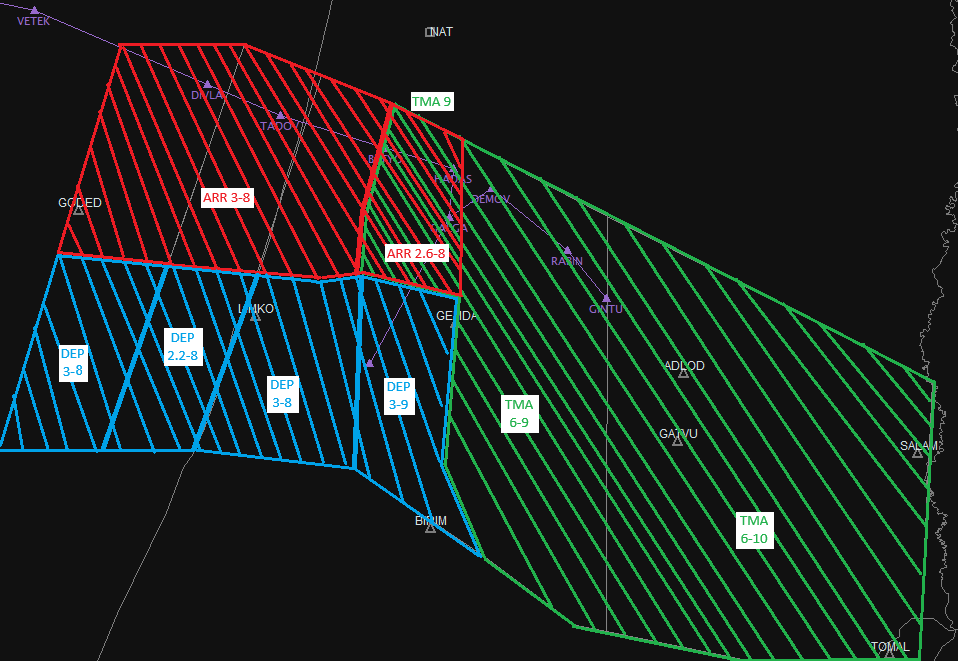
Annex B: APP-DEP-TMA SECTORS ILS 30
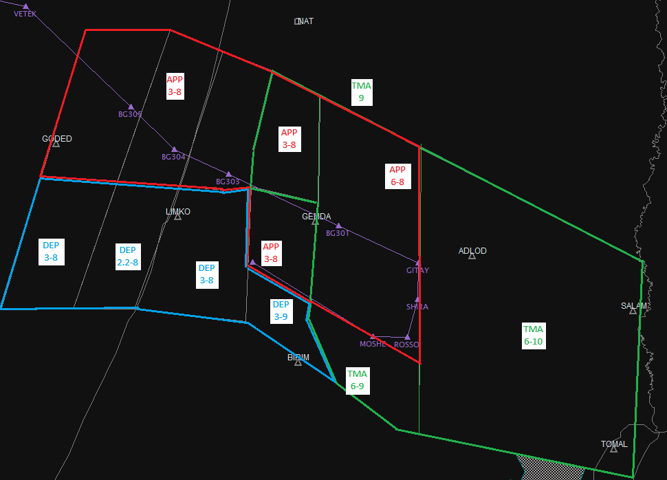
Annex C: APP-DEP-TMA SECTORS RNP-Z 30
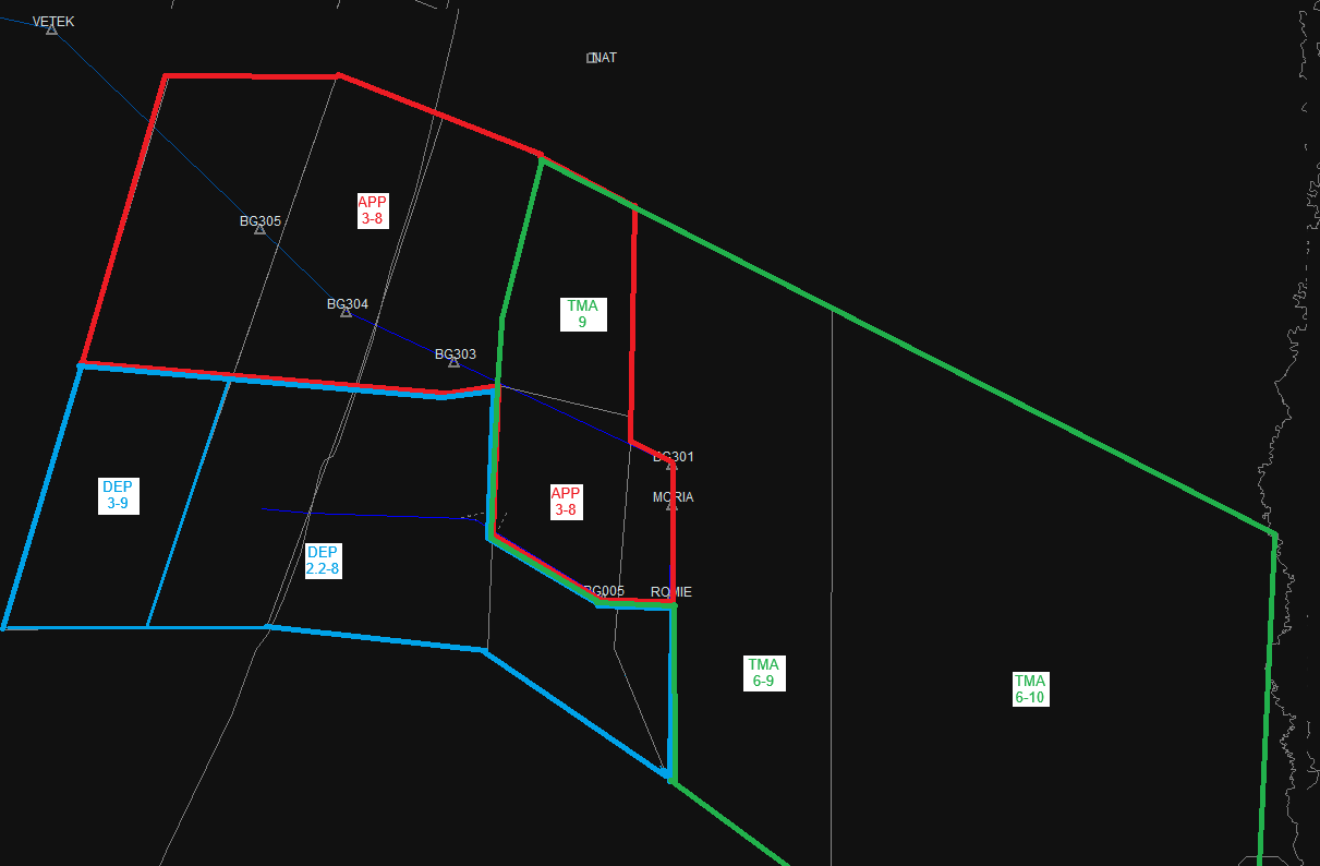
ANNEX D: APP-DEP-TMA SECTORS ILS 26
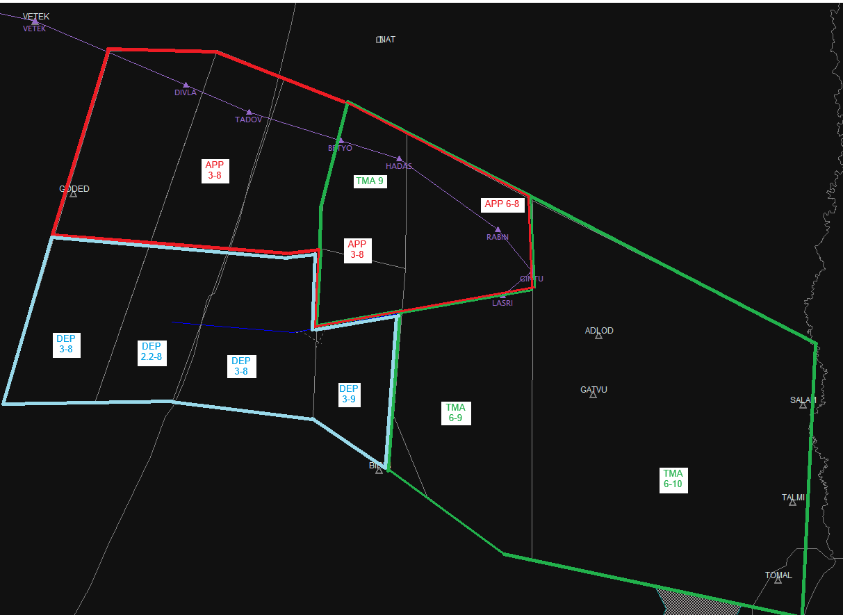
ANNEX E: APP-DEP-TMA SECTORS 08/08 OR 26/12 OR 12/12 OR South approach to 30
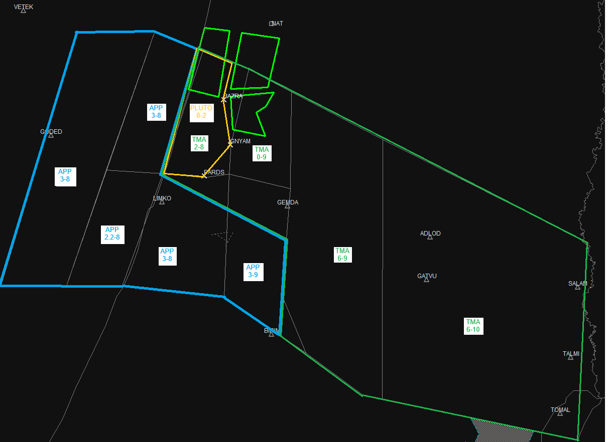
ANNEX F: Checklist switch to configuration 26/21
Reports
ü Pluto (Or Apollo)
ü ACCS (Specify about inbound to the TMA via SIVAK-TALMI-GATVU)
ü ACCN (Rerouting, Spacing, Working Freq)
Technical systems
ü Confirm ILS is active (NOTAM)
ü Confirm configuration is updated at Vatis
ANNEX G: Checklist switch from configuration 26/21
Staffing
ü Marge DEP sector into TMA
Reports
ü Pluto (Or Apollo)
ü ACCS (Back to normal routing)
ü ACCN (Rerouting, Configuration, Spacing, Working Freq)
Technical systems
ü Confirm configuration is updated at Vatis
ANNEX H: Checklist for integration to runway 30 while 26/21
· Intended to integrate between 3-1 planes for runway 30
|
Switch from 21 to 30 · Define to Radar and Tel-Aviv ACC: - Last Airplane to land on 21 - Last Plane to land on 30 · Coordinations: - Tel-Aviv 30NM between the last for 21 and the first to 30 - Tel Nof if required to active GAVRI/RNP-X (10 min before active and if online) · Brief the DEP controller: - Send the inbound traffic to 30 to TWR-DEP - No traffic shall cross LIMKO before the landing plane on 21 crosses the runway threshold |
Switch from 30 to 21 · Define to Radar and Tel-Aviv ACC: - Last Airplane to land on 21 - Last Plane to land on 30 · Coordinations: - Tel-Aviv 20NM between the last for 30 and the first to 21 - Tel Nof if were active GAVRI/RNP-X when finished · Brief the APP controller: - Inbound traffic to 21 shall not cross 6NM final before the landing on RWY30 crossed RWY30 threshold
|
Annex I: BGN APC Logon Order
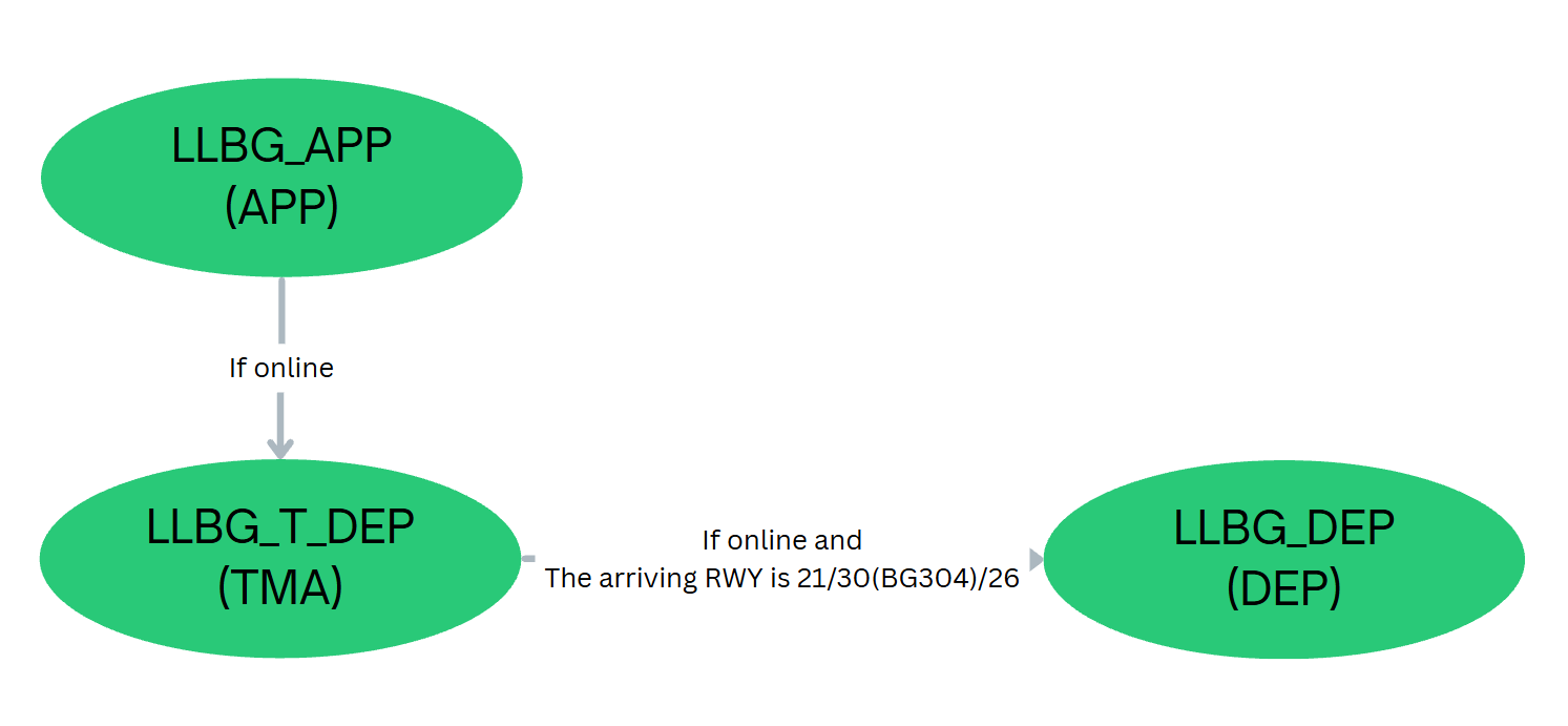
VATIL - CVACC || LOA
Letter of Agreement between CvACC (LCCC) and VATIL (LLLL)
1. General
1.1 Purpose and Scope:
The purpose of this Letter of Agreement is to define the coordination procedures to be applied between NICOSIA ACC[1] and TEL AVIV ACC[2] when providing ATS to GAT[3] and OAT[4].
The procedures contained in this operational letter of agreement that supplement or detail, when so required, the procedures contained in documents of the two States, ICAO and Eurocontrol shall be applied to all aircraft that cross the common boundary of the Nicosia and Tel Aviv FIRs.
1.2 Operational Status
The two ATS units concerned shall keep each other advised of any changes in the operational status of their facilities and navigational aids, which may affect the procedures specified in this Letter of Agreement. Information concerning the flow of traffic such as weather, overload, navigation aid or any other relevant information shall be passed on the concerned Unit.
2. Geographical responsibility for the provision of ATS.
2.1 Areas of responsibility
2.1.1 NICOSIA ACC
Lateral limits: As published in AIP CYPRUS
Vertical limits: As published in AIP CYPRUS
2.1.2 TEL AVIV ACC
Lateral limits: As published in AIP State of ISRAEL
Vertical limits: As published in AIP State of ISRAEL
2.2 Delegation of The responsibility for The Provision of ATS
Routing: Traffic between Nicosia and Tel Aviv FIRs should route as indicated below, or as coordinated between the controllers in charge (Example: direct DESPO/STEPA/VELOX).
a) Westbound to Nicosia FIR:
· SUVAS – TEZAK
· SUVAS - STEPA
b) Northbound to Nicosia FIR:
· DAFNA – VELOX
· MERVA – VELOX/DESPO
c) Eastbound to Tel Aviv FIR:
· IDAKU – PIKOG
· LEDRA – PIKOG
· BIRES- PIKOG
· BIRES – KEREN[5]
d) Southbound to Tel Aviv FIR:
· ZOMBA – AZERE
· ZOMBA - MERVA[6]
3. Procedures for coronations
3.1 Tel-Aviv clearance limit outbound flight from LLBG/LLHA to Nicosia FIR
a. All outbounds flights, Tel-Aviv ACC Clerance limits FL260 or Below
b. Directs may be given by Tel Aviv ACC to VELOX without prior coordination, any other waypoints require coordination with NICOSIA ACC.
3.2 Overflight to Nicosia FIR (West/North bound)
a. All outbound traffic from OJAI/OJAM/LLER/LLNV clearance limit is FL320
b. Any other outbound traffic clearance limit is RFL
3.3 Nicosia clearance limit Inbound flights to LLBG/LLHA/LLER
a. Eastbound traffic: Nicosia ACC shall clear traffic decent to FL210 before crossing N71 Airway, subject to traffic flow and separation. But no lower than FL210
b. Southbound traffic: Nicosia ACC shall clear traffic decent to FL270 before crossing N71 Airway, subject to traffic flow and separation. But no lower than FL270
c. LLHA: Nicosia ACC shall clear traffic decent to 8000ft before crossing 70NM before MERVA[7], subject to traffic flow and separation. But no lower than 8000ft
d. Best Practice: All inbound traffic recommended crossing N71 Airway FL310 or below
e. Two or more aircrafts with less than 15NM separation at the same direction, will be separated by vertical separation of 2,000 ft (e.g. first aircraft descending to FL210, second aircraft to FL230)
f. Overflow: In the condition that Tel-Aviv ACC declares overflow, the default practice shall be giving hold as published in the positions of AZERE[8] and PIKOG[9] between FL210 to FL340 While remaining under Nicosia ACC, the traffic will be transferred to Tel-Aviv ACC after leaving the hold.
3.4 Overflight to LLLL FIR (East/South bound)
a. All traffic should cross N71 Airway at RFL (FL330 or above).
· Traffic below FL330 must be coordinated with LLLL FIR
4. Transfer of Control & Communication
4.1 Release Points
Traffic release to Tel-Aviv ACC as soon as crossing N71 Airway.
Westbound: Traffic release to Nicosia ACC no later than waypoint SUVAS
Northbound: As soon as possible, subject to traffic flow and potential conflicts, but no later than FIR boundaries.
4.2 Frequencies:
Nicosia ACC: 124.200 MHz
Nicosia South ACC: 124.200 MHz
Nicosia East ACC: 126.300 MHz
Tel Aviv ACC: 121.400 MHz
Tel Aviv Enroute ACC: 132.025 MHz[10]
4.3 Traffic Transfer
 All traffic from LLLL FIR to Nicosia FIR should be transferred to LCCC_CTR
All traffic from Nicosia FIR to LLLL FIR should be transferred to LLLL_CTR
· Incase LLLL_CTR if offline, traffic bound/destination to LLBG should be transferred to LLBG_APP, following the same procedures as with LLLL_CTR, following the same procedures as with LLLL_CTR
· Overflight to LLLL FIR would be passed to LLLL_CTR or LLLL_E_CTR only. Incase these units are offline, LCCC_CTR will send the aircraft to Unicom when clear of conflict.
5. Validity
Last review: Febuary 9, 2026 – Revision 1.3
[1] LCCC_CTR
[2] LLLL_CTR
[3] General Air Traffic
[4] Operational Air Traffic
[5] Intended for TFC crossing LLLL FIR (Over ben Gurion at high altitude)
[6] Intended for TFC Inbound to LLHA/LLIB or crossing LLLL FIR (Over ben Gurion at high altitude)
[7] The vicinity of VELOX/ZOMBA/DESPO.
[8] Right hold, Inbound: 172, 1.5 min, max IAS 300kts.
[9] Left hold, Inbound: 123, 1.5 min, max IAS 300kts.
[10] Overflight only
VATIL JorvACC LOA
VATIL irtual Is The New Reality
Letter of Agreement (LOA)
Between: Amman ACC (JOVACC / OJAC) And: Tel Aviv ACC (VATIL / LLLL)
Updated: As of 14 May 2026.
Effective Date: 15 May 2026
JOVACC VATSIM Jordan
Source: AIP ISRAEL (ENR 1.5, ENR 2.1) and applicable Jordan AIP/SUP (Rev 2509/Sep 2025) material as current.
1. General
1.1 Purpose
Defines ATS coordination between Amman ACC and Tel Aviv ACC for IFR/VFR traffic crossing the common FIR boundary.
1.2 Applicability
Applies to all aircraft crossing between the Amman FIR and Tel Aviv FIR when both ATS units are operational.
Operational status (navaids outages, weather, FPL issues, restrictions) that affects ATS provision shall be coordinated immediately.
2. FIR Areas & ATS Airspace
2.1 FIR Boundaries
Tel Aviv FIR
Lateral + vertical limits are as defined in ISRAEL AIP ENR 2.1:
Full FIR from UNL to GND
-
Airspace classifications: A, C, D as published.
Amman FIR
As published in JORDAN AIP (ENR sections).
2.2 Mandatory Reporting/Entry Points
Flights entering Tel Aviv FIR from Amman FIR shall use published entry reporting points:
-
RALNA or OSAMA waypoints for Tel Aviv Inbounds.
-
MUVIN or TALMI waypoints for Tel Aviv overflights departing from the Amman FIR.
Flights entering Amman FIR from Tel Aviv FIR shall use published entry reporting points:
-
SALAM or RALNA waypoints for Amman Inbounds.
-
OSAMA SALAM RALNA and or MUVIN/TALMI waypoints for Amman overflights departing from the Tel Aviv FIR.
Note: Entry via other points is prohibited unless explicitly cleared by ATC.
3. Standing agreements
3.1 Tel Aviv ACC -- Amman ACC
-
➤ All traffic shall hold cleared altitude 5NM Prior to transfer [unless said otherwise]
-
➤ All traffic shall be separated with lateral separation of 10NM at least unless maintain vertical separation.
-
➤ When transfer of control is performed the traffic shall be with 45 deg of clear area until entering receiving units' airspace.
3.1.1 Tel Aviv ACC to Amman ACC
|
Inbound |
Altitude |
Condition |
|---|---|---|
|
SALAM (enroute) |
FL360 or above |
|
|
SALAM (enroute) |
28,000ft ALT holding |
|
|
OJAI |
15,000-11,000 |
➤ Depends on traffic at LLLL airspace ➤ Until SALAM the traffic shall maintain LLBG-QNH |
3.1.2 Amman ACC to Tel Aviv ACC
|
Inbound |
Altitude Condition |
|---|---|
|
MOUAB |
FL350 or above |
|
Departing TRFC |
12,000ft at MOUAB Cleared 14,000 Higher levels maybe coordinated especially when 08's OJAI ops or 06 OJAM ops in use. Maximum allowable is per ATC (usually FL280) |
3.2 Ben Gurion -- Amman ACC
-
➤ All traffic shall hold cleared altitude 5NM Prior to transfer [unless said otherwise]
-
➤ All traffic shall be separated with lateral separation of 10NM at least unless maintain vertical separation.
-
➤ When transfer of control is performed the traffic shall be with 45 deg of clear area until entering receiving units' airspace.
3.2.1 Ben Gurion to Amman ACC
|
Inbound |
Altitude |
Condition |
|---|---|---|
|
OJAI/OJAM |
11,000ft at SALAM and 9,000ft at RALNA |
The inbound traffic shall descend on LLBG QNH until LLLL FIR boundary. Handoff to OJAI should be within 5nm of SALAM and no later. |
|
Overflies of Amman TΜΑ |
Maximum 9000ft at SALAM |
Enter SALAM at 9000ft and no higher unless coordinated. Higher Altitude is subject to Amman ACC approval |
3.2.2 Amman ACC to Ben Gurion
|
Inbound |
Altitude |
Condition |
|---|---|---|
|
LLBG |
10,000ft/8,000ft at OSAMA |
The inbound traffic shall descend on Amman/OJAC QNH |
4. Coordination and Procedures with Adjacent Units
4.1 Ben Gurion - Amman ACC
-
➤ If traffic is unable to hold cleared altitude 5NM before transfer of control the adjacent unit shall be updated
-
➤ Inbound to LLBG: OSAMA at 6000ft shall be coordinated as soon as possible (at least 5 min prior to the position)
4.2 Tel Aviv - Amman ACC
-
➤ If traffic is unable to hold cleared altitude 5NM before transfer of control the adjacent unit shall be updated
-
➤ Inbound to Amman ACC (Enroute): Any traffic crossing below FL350 shall be coordinated
-
➤ Inbound to Tel Aviv ACC (Enroute): Any traffic crossing below FL360 shall be coordinated [Except for FL280]
FL280 may be closed due to MIL corridor, in this case Tel Aviv ACC will update Amman ACC with 10 min prior for closure. In that situation the block altitude of FL280 need to be coordinated.
5. Frequencies
Tel Aviv ACC:
|
Identification |
FREQ |
Transfer\Reason |
|---|---|---|
|
LLLL_CTR (Bandbox) |
121.400 |
|
|
LLLL_D_CTR |
122.950 |
Departing traffic from OJAI |
|
LLLL_A_CTR |
121.400 |
Inbound traffic to OJAI |
|
LLLL E CTR |
132.025 |
Enroute traffic |
|
LLBG_D_APP (Bandbox) |
120.500 |
Arriving to LLBG\LLHA\Low altitude enroute flights |
|
LLBG_A_APP |
131.100 |
Shall be coordinated in start of shift, acting as LLBG_APP |
|
LLBG_T_APP |
119.500 |
Amman ACC:
|
Identification |
FREQ |
Transfer\Reason |
|---|---|---|
|
AMM APP |
128.900 |
All inbounds to Amman TMA including OJAI and OJAM Departures from Tel Aviv towards the east |
|
OJAC_CTR |
128.500 |
When AMM APP is offline, OJAC will assume its responsibilities, therefore traffic will be handed off to OJAC in case of AMM APP being offline All other overflying traffic with not a destination set as OJAI/OJAM shall be transferred to Amman Control given their altitude/FL is below FL250. |
6. Airspace & Altimetry Considerations
-
RVSM: Applicable within Tel Aviv FIR between FL290 and FL410 per ICAO EUR procedures.
-
Flight levels and altitude blocks: Follow published AIP route altitude restrictions and chilling levels for each airway/point as amended.
7. Validity & Amendments
-
This LOA reflects the most recent AIP information available (as of 14 May 2026). It supersedes earlier local agreements and NOTAM-derived procedures, but must be verified operationally with AIP and NOTAM.
Signed:
Dalon
کیں
Nadeem Zabaneh ACCJO4ATC Director
Jordan VACC - VATSIM Network
14-May-2026
Yuval Gazit-VATIL3-ATC Director
VATIL - VATSIM Network
14-May-2026
LOA - VATSIM USE ONLY - OJAC and LLLL - 2026
GEN | נהלי כלליים - General Procedures
העברת מכ"ם -- RADAR TRANSFER
מטרת נוהל זה היא להסדיר את שיטת העברת הלייבל (העברת TAG) בין עמדות המכ"ם במרחב LLLL, נוהל זה מבוסס על החוסר התיאום הטכני בין הבקרות במציאות
- בהעברה בין בקרות במרחב יש לבצע רליס (RELEASE) ללייבל (TAG) {בין בקרות}
- במהלך העברת תנועה בין ת"א לגישה ולהפך יש לבצע על פי הנוהל הבא:
- העברת הלייבל אל העמדה הקולטת
- העמדה הקולטת תאשר את הלייבל
- העמדה הפולטת תבצע העברת קשר לתנועה
This procedure defines the way in which a tag is transferred between radar positions in the LLLL FIR; this procedure is based upon the premise that there is no technical contact between LLLL FIR positions and the LLLL FIR and Eurocontrol radars.
A. When transferring control between radar station wethin LLLL FIR the emitting station shall RELEASE instead of TRANSFER
B. This sequence of events shall describe the transfer of control between LLLL and LLBG radar stations.
- Transfer of label to the receiving station
- The receiving station shall accept the label
- The emitting station shall perform radio transfer
עדכון נהלים - Update of procidures
1.Method
1.1 Each controller at the LLLL fir shall follow updated information and follow the priority of documentation
1.2 Proyirity of documentation
1.2.1 NOTAMS as published by Vatils Operation department or by its certified replacement (ETC control room shift manager)
1.2.2 Ammendments published at briefing section
1.2.3 SOP as published in this wiki or by Vatil ops department
1.2.4 Traning material approved by VATIL 3 or by certified mentor
1.3 When an ammendment to the SOP is occurring the following thing shall happen
1.3.1 VATIL 7 Shall realesse small berifing (read and sign) about the relevant sections and documentation
1.3.2 While updating the SOP for a duration of one month the update shall be marked in yellow and linked to a relevant berofing with updates about implementations.
1.4 When NOTAM is active for prolong time it shall be published in the berifing area also as NOTAM
2. Roles and reponsibilities
2.1 Vatil 7 - OPS Director
2.1.1 Vatil 7 shall maintain the SOP Updated and release berifing about upcoming changes
2.1.2 VATIL 7 Or ops department member shall publish relevant NOTAMS in the the ATS distribution
2.2 Vatil 3 - Traning Director
2.2.1 Vatil 3 shall confirm the learning material is updated or the student have the ability to confirm that their knowledge is updated
2.3 Standard controller
2.3.1 Each controller shall check before an AIRAC update or whsn recived indication of any change for changes in the briefing section of the SOP and for implementation in the SOP
2.3.2 While preforming shift change the reliving controller shall confirm with three relifed controller about active Ammendments.
Berifing Area
Structure
This section contains Instructions and Notices to controllers, providing notice of changes to ATC Procedures either on a permanent or temporary basis. Instructions are categorised as follows:
- Permanent Instructions (PI) - Amendments to procedures or the introduction of new procedures.
- Temporary Instructions (TI) - Temporary changes to ATC procedures, such as non-standard sector splits or airspace restrictions, including for military activity. Some TIs may be optionally implemented.
- ATC Notices (NOT) - General information, which may include reminders of non-local procedures, or notice of changes to functionality in the control programs
TI - 26 - 10 - 01
| Valid | Until further notice |
| Applicable to | LLSC,LLBG |
| Status | Active |
| Mandatory | Yes |
| Implemantation in SOP | N/A |
Summery
Due to military activity on J10 any civilian flight between SIVAK <-> NURIT Shall not cross above 18,000ft, lower and lateral limit is not affected
Exceptions -
- Flights refusing to decent
- Flight to military bases (For example Nevatim, Ramon Etc
TI - 26 - 10 - 02
| Valid | until 31/12/2026 |
| Applicable to | LLLL |
| Status | Active |
| Mandatory | no |
| Implemantation in SOP | N/A |
Summery
Airway L53 is closed between ABIMI - BGN VOR The following re routes shall be in effect (either by vectors or by route ammendment)
| Civil |
Departure: AMMAN FIR | TALMI DCT TAPUZ | 11000ft-16000ft |
| Departure:LLOV, LLER, LLNV to LCCC ctr | GOBRI DCT TAPUZ | 11000ft-16000ft | |
| Military |
Overfly from AMMAN FIR | TALMI DCT TAPUZ | 17000ft or greater |
| Overtly from LLER/LLOV/LLNV to LCCC ctr | GOBRI DCT TAPUZ | 17000ft or greater |
Exceptions -
- Flights refusing to decent or re route
TI - 26 - 10 - 03
| Valid | until 31/12/2026 |
| Applicable to | LLLL |
| Status | Active |
| Mandatory | no |
| Implemantation in SOP | N/A |
Summery
Airway N134 is closed between VOLFO. - SALAM Available at block altitude of 11000ft - 16000ft for civilian aircraft
Military traffic may use block of 17,000 ft or greater
Exceptions -
- Flights refusing to decent or re route
TI - 26 - 10 - 04
| Valid | until 31/12/2026 |
| Applicable to | LLSC |
| Status | Active |
| Mandatory | no |
| Implemantation in SOP | N/A |
Summery
Airway Q30 is closed between BEXOM - NURIT
Exceptions -
- Military traffic or military charter (AYT Etc)
TI - 26 - 10 - 05
| Valid | until 31/12/2026 |
| Applicable to | LLHZ |
| Status | Active |
| Mandatory | YES |
| Implemantation in SOP | N/A |
Summery
Due to radio jamming LLHZ_TWR Is active on 125.600 Mhz and LLHZ_DEL Is active on 118.550
PI - 26 - 10 - 06
| Valid | PARMENET |
| Applicable to | LLHA |
| Status | Active |
| Mandatory | YES |
| Implemantation in SOP | No |
Summery
Parking position J10 is closed
PI - 26 - 10 - 07
| Valid | PARMENET |
| Applicable to | LLHA |
| Status | Active |
| Mandatory | YES |
| Implemantation in SOP | No |
Summery
Clearance delivery isoperation on 121.800 Mhz
TI - 26 - 10 - 08
| Valid | until further notice |
| Applicable to | LLIB |
| Status | Active |
| Mandatory | No |
| Implemantation in SOP | No |
Summery
Traning area A and B are closed
TI - 26 - 10 - 09
| Valid | 31/10/26 |
| Applicable to | LLIB |
| Status | Active |
| Mandatory | No |
| Implemantation in SOP | No |
Summery
For civilian flights departures approved only southbound
TI - 26 - 10 - 10
| Valid | until further notice |
| Applicable to | LLER |
| Status | Active |
| Mandatory | Yes |
| Implemantation in SOP | No |
Summery
RNAV Departures are not approved due to GNSS interference
TI - 26 - 10 - 11
| Valid | until further notice |
| Applicable to | LLER |
| Status | Active |
| Mandatory | no |
| Implemantation in SOP | No |
Summery
Traning area Har Berecb is closed